Next Generation Solenoid Driver
Evaluation Kit User Manual
About this document
This document explains how the Evaluation Kit for the NextGen Solenoid Driver ICs TLE92464ED and
TLE92466ED are taking into operation. The required hardware and software components for the evaluation of
the Next Gen Solenoid Driver IC TLE92464ED/TLE92466ED are documentated. See the TLE92464ED/TLE92466ED
datasheet for a detailed description of the device.
Note: All references of the TLE92464ED Evaluation board within this document are also valid for
TLE92466ED Evaluation board.
Intended audience
This document is intended for anyone who uses the Next Gen Solenoid Driver Evaluation Kit.
Table of contents
About this document ....................................................................................................................... 1
Table of contents ............................................................................................................................ 1
1 Hardware .............................................................................................................................. 2
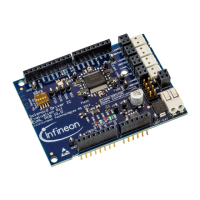
1.1 Eval PCB ................................................................................................................................................... 2
1.1.1 Connector Interface for Arduino ........................................................................................................ 4
1.1.2 Jumper Options ................................................................................................................................. 7
1.1.3 LEDs .................................................................................................................................................... 7
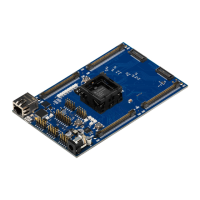
1.2 Connection PCB ....................................................................................................................................... 7
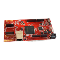
1.2.1 Connector Interface for TriBoard TC277 ........................................................................................... 8
1.2.2 Jumper Options ................................................................................................................................. 9
1.3 Version S setup ........................................................................................................................................ 9
1.4 Version L setup ...................................................................................................................................... 11
1.5 Schematics ............................................................................................................................................ 11
2 Software .............................................................................................................................. 22
2.1 Flashing/Updating Aurix TC277 Software ............................................................................................ 22
2.2 Flashing/Updating XMC Software ......................................................................................................... 22
2.3 XMC for Arduino IDE .............................................................................................................................. 23
2.4 Graphical User Interface (GUI) .............................................................................................................. 24
2.4.1 Main Window .................................................................................................................................... 24
2.4.2 Evaluation Board Tabs ..................................................................................................................... 25
2.5 Information on the GUI communication interface............................................................................... 27
2.5.1 List of Commands ............................................................................................................................ 27
Revision history............................................................................................................................. 30