EasyManua.ls Logo

Infineon TriBoard TC3X9 TH User Manual

Infineon TriBoard TC3X9 TH
57 pages
To Next Page IconTo Next Page
Page #1 background imageLoading...
Page #1 background image
User Manual Please read the Important Notice and Warnings at the end of this document V2.1
www.infineon.com
TriBoard TC3X9 TH V2.0(1) and TriBoard TC3X9 V2.0 2017-11
TriBoard TC3X9
TriBoard Manual TC3X9
Hardware: TriBoard TC3X9 TH V2.0(1) and TriBoard TC3X9 V2.0
About this document
Scope and purpose
The User Manual provide information about using, configuration and connecting the TriBoard with Infineon
AURIX™ TC3X9 device. The manual provide information for different hardware types. There exist different
hardware with Through Hole socket (TriBoard TC3X9 TH) and soldered devices (TriBoard TC3X9). The schematic
is identically for the all boards if not other mentioned in chapter schematic. The placing on the boards is
identically, all components are on the same location. Only the routing is different (socket need more space and
has through hole). All figures are valid for each board if not differently mentioned.
Intended audience
Design, verfication, test and software engineers will use this document to get an understanding of the
functionality and connections of the TriBoard.

Table of Contents

Question and Answer IconNeed help?

Do you have a question about the Infineon TriBoard TC3X9 TH and is the answer not in the manual?

Infineon TriBoard TC3X9 TH Specifications

General IconGeneral
BrandInfineon
ModelTriBoard TC3X9 TH
CategoryMotherboard
LanguageEnglish

Summary

Features

Summary of Features

Lists key features of the TriBoard.

Block Diagram

Visual representation of the board's architecture.

Component Placement

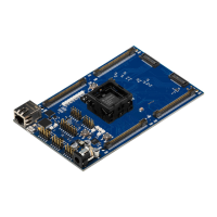
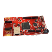
Shows the physical layout of components on the board.

Connectors

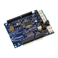
Lists the types of connectors available on the board.

Components

Lists major components on the board.

TriBoard Information

Usable Devices

Lists compatible microcontroller devices for the board.

Failsafe Handling and LEDs

Explains error handling and describes onboard LEDs.

USB Connector

Details the USB interface for PC connection.

miniWiggler JDS Debug Tool

Describes the miniWiggler JDS debug tool.

FlexRay (E-RAY) Interface

Details the FlexRay communication interface.

Debug System Overview

Provides an overview of the debug system.

External Memory Options

Details available external memory configurations.

Serial Connection to PC

Describes PC serial communication setup.

Power Supply System

Describes the board's power supply generation.

TriBoard Configuration

HW Boot Configuration

How to configure boot settings via DIP switches.

Bootmode Selection

Settings for different boot modes.

Signal (on board used) Description

Debug Signals

Lists and describes debug signals.

Connector Pin Assignment

TC3X9 Connector / Top View Pinout

Pinout details for the main TC3X9 connector.

Schematic and Layout

Component Layout Diagrams

Shows the physical placement of components.

Schematic Diagrams Overview

Refers to the schematic diagrams for the project.

Related product manuals