EasyManua.ls Logo

Infineon TLE987 Series

Infineon TLE987 Series
35 pages
To Next Page IconTo Next Page
Loading...
TLE987x EvalBoard
About this document
Scope and purpose
This user manual is intended to help users using the TLE987x EvalBoard. This EvalBoard is designed to evaluate
hardware and soware functionalities of the TLE987x device family.
This manual provides additional information about the layout, jumper settings, interface and debug options. It
introduces the evaluation platform as well as how to write soware and download it to the TLE987x.
The TLE987x is available in VQFN and a brand-new TQFP package, this document is valid for both.
Intended audience
This document is for everyone who works with the TLE987x EvalBoard.
User Manual Please read the Important Notice and Warnings at the end of this document v1.0
www.infineon.com 2020-07-30
Question and Answer IconNeed help?

Do you have a question about the Infineon TLE987 Series and is the answer not in the manual?

Infineon TLE987 Series Specifications

General IconGeneral
SeriesTLE987
CoreARM Cortex-M3
Operating Frequency40 MHz
Operating Voltage3.0 V to 5.5 V
Communication InterfacesSPI, UART, LIN

Summary

About this Document

Scope and Purpose

Outlines the manual's intent and the EvalBoard's function.

Intended Audience

Identifies users for whom the document is intended.

Abbreviations and Definitions

Concept

Interconnects

Banana Jacks for Ground, Supply, and LIN

Banana jack connections for power, ground, and LIN communication.

Banana Jacks for Motor Connection

Banana jacks for connecting to motor half-bridges.

uIO Stick Connector

16-pin header for bootstrap loader and LIN programming.

Test Points and LEDs

Test Points Overview

Lists various test points for monitoring signals and voltages.

LED Indicators

Describes status LEDs for power and communication.

Jumper Settings

Reset, LIN, and Monitor Jumpers

Configures RESET, MON buttons, and LIN termination.

Status LED and Current Measurement Jumpers

Controls VDDEXT LED and current measurement.

Sensor Interface and Debugger Jumpers

Configures TMR interface and SWD debugger.

POTI Supply and Signal Jumper Configuration

Configures POTI supply and signal pin assignments.

Hall and SPI Jumper Configuration

Configures Hall sensor and SPI interface pin assignments.

Communication Interfaces

LIN Communication

Describes LIN communication via banana jack and uIO BSL interface.

Debugging Interface

Explains debugging via on-board debugger and SWD interface.

Software Toolchain

Keil Vision5 IDE

Recommended Integrated Software Development Environment.

Infineon ConfigWizard

Tool for speeding up IC programming and code configuration.

TLE987 x SDK

Software Development Kit with code examples.

Debug Connection Setup

Steps for configuring Flash and Debug connection with J-Link.

Technical Data

Optional Additional Placements

External Oscillator and Capacitors

Components for external oscillator and filtering.

High-Side MOSFET Snubbers and Capacitors

Components for high-side MOSFET protection and filtering.

Low-Side MOSFET Snubbers and Capacitors

Components for low-side MOSFET protection and filtering.

Phase 2 High-Side MOSFET Snubbers

Components for Phase 2 high-side MOSFET snubbing.

Schematics and Layout Baseboard

Schematics Baseboard

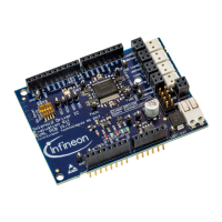
Electrical diagrams of the baseboard circuitry.

Layout Baseboard

Physical layout of the baseboard layers (top, power, ground, bottom).

Schematics and Layout VQFN Socket

Schematics VQFN Socket

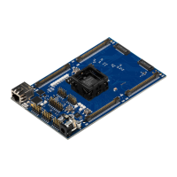
Electrical diagram of the VQFN socket interface.

Layout VQFN Socket

Physical layout of the VQFN socket (top and bottom layers).

Schematics and Layout TQFP Socket

Schematics TQFP Socket

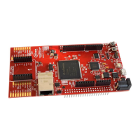
Electrical diagram of the TQFP socket interface.

Layout TQFP Socket

Physical layout of the TQFP socket (top and bottom layers).

Revision History

Related product manuals