3 Test points and LEDs
GND
GND
GND
GND
OP1
GND
GND
VBAT
SH3
SH2
SH1
SH1
VDH
GH1
GH2
VDH
SH2
GND
GL2
GH2
VDH
GND
SH3
VCP
VS
GL1
OP2
GL3
LEDCOM
LEDBAT
LED
VDDEXT
LED1-8
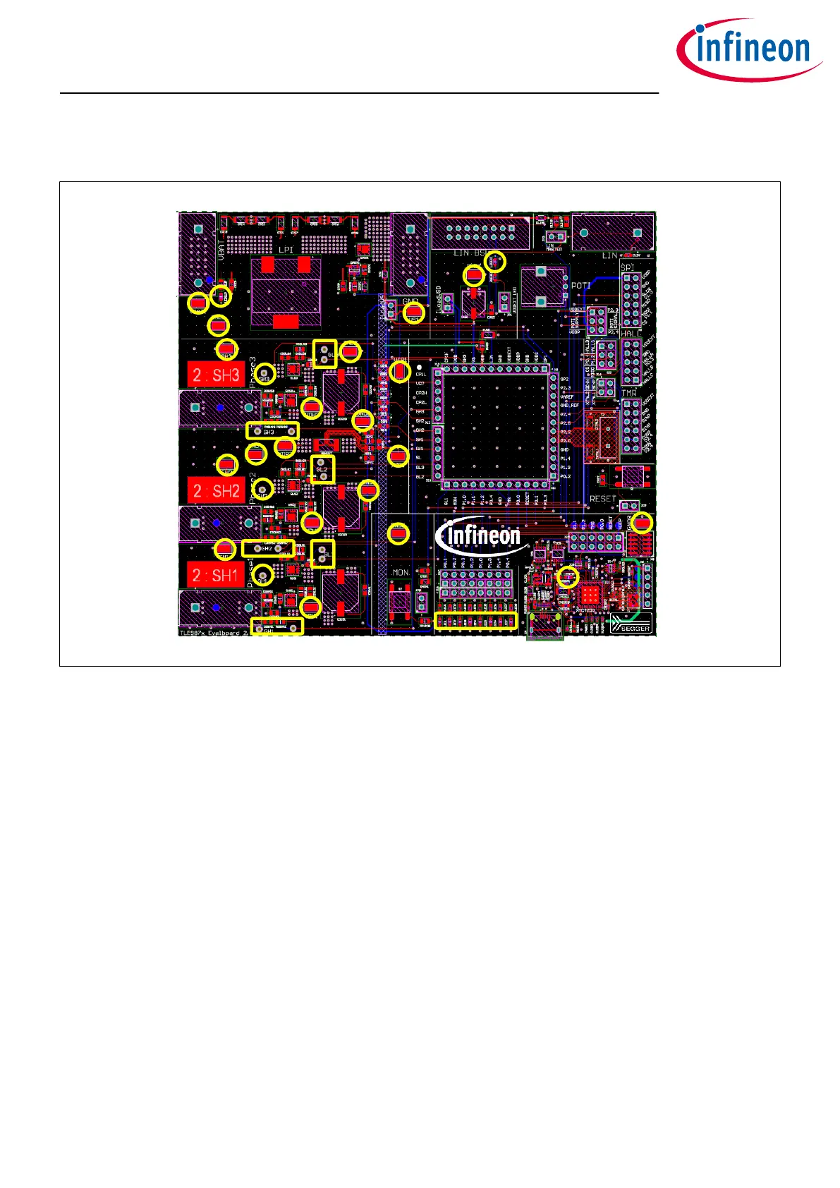
Figure 8 Test points
Test points
• 2× VBAT
• 1× VS
• 1× VCP
• 8× GND
• 2× SH1, 2× SH2, 2× SH3
• 2× GH1, 2× GH2, 2× GH3 (for gate-current supervision)
• 3× GH1, 3× GH2, 3× GH3 (for gate-current supervision).
• OP1, OP2
• 3× VDH
LEDs
• LEDBAT (supply voltage active)
• LEDCOM (on-board debugger communication active)
• LEDVDDEXT (VDDEXT active)
• LED1-8 can be connected to GPIOs (see Table 1)
TLE987x EvalBoard
3 Test points and LEDs
User Manual 9 v1.0
2020-07-30

 Loading...