2
4 6
1
3 5
8 10
7 9
HALL C HALL B HALL A GND VDDEXT
HALL C HALL B HALL A GND VDDEXT
Figure 6 Pin configuration Hall sensor interface
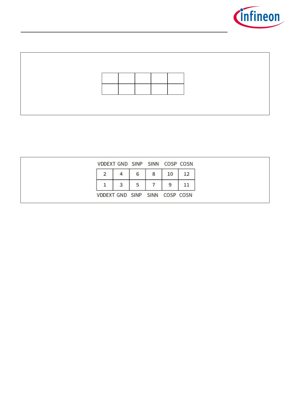
Pin header for TMR sensor interface
The 10-pin header (2 × 5) with 2.54 mm pitch can be used for controlling external TMR sensors. In order to
access the TMR sensor interface, the jumpers SINN and SINP have to be set.
Figure 7 Pin configuration TMR sensor interface
TLE987x EvalBoard
2 Interconnects
User Manual 8 v1.0
2020-07-30

 Loading...