15
13 11 9 7 5 3 1
16
14 12 10 8 6 4 2
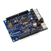
N.C. N.C. N.C. N.C. RESET LIN N.C. NC.
N.C. N.C. N.C. N.C. N.C. VS N.C. GND
Figure 3 Pin configuration uIO BSL
USB for on-board debugger
The on-board connector can be accessed with a micro-USB cable, connected to a PC.
Pin header for SWD
The 10-pin header (2 × 5) with 1.27 mm can be used for debugging if the on-board debugger is not available or if
it cannot be used.
2
4 6
1
3 5
8 10
7 9
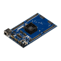
TMS P0.0 N.C. N.C. RESET
5V GND GND N.C. PORST
Figure 4 Pin configuration SWD interface
Pin header for SPI
The 12-pin header (2 × 6) with 2.54 mm pitch can be used for controlling an external IC with the SPI. In order to
access the SPI, the jumpers P0.4 and P1.2 have to be set in position 2.
2
4 6
1
3 5
8 10
7 9
12
11
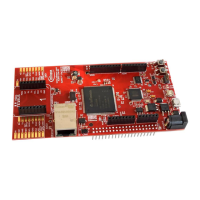
VDDP GND SCLK MISO MOSI CS
VDDP GND SCLK MISO MOSI CS
Figure 5 Pin configuration SPI
Pin header for Hall sensor interface
The 10-pin header (2 × 5) with 2.54 mm pitch can be used for controlling external Hall sensors. In order to access
the Hall sensor interface, the jumpers P0.4 and P1.2 have to be set in position 1.
TLE987x EvalBoard
2 Interconnects
User Manual 7 v1.0
2020-07-30

 Loading...