User Manual 3-1 V2.1
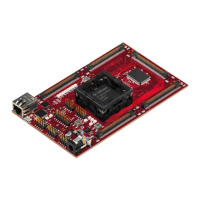
TriBoard TC3X9 TH V2.0(1) and TriBoard TC3X9 V2.0 2017-11
TriBoard Manual TC3X9
Hardware: TriBoard TC3X9 TH V2.0(1) and TriBoard TC3X9 V2.0
TriBoard Information
3 TriBoard Information
3.1 Usable devices
The board can be used with the following devices:
– TC399 A-Step (Ethernet and seond HSCT will not work in this case because device don’t support RGMII and
don’t have second HSCT)
–TC399 B-Step
– TC397 A-Step (Ethernet will not work in this case because device don’t support RGMII, external flash and
sram not usable)
– TC397 B-Step (external flash and sram not usable)
– TC389 A-Step (only if external flash and sram not assembled)
– TC387 A-Step (external flash and sram not usable)
Note: TC3X7 can be used with the innerballs (center) of BGA516, in this case all signals on the external 2
rows/colums are not connected/used.
Note: Please check always the latest manual for complete list of usable devices.
3.2 Differences between TC389 and TC399
Main difference between TC389 and TC399 is that the TC389 don’t had an external bus unit (EBU). Also the
corresponding VEBU pins of TC399 are connected to VEXT on TC389. Therefore you can’t use a TC389 in a board
assembled for TC399. The soldered boards always will have the correct assembling. For TriBoard TC3X9 TH
(socket variante) use with care.
Note: If the board has assembled external flash and sram then this
socket board can be used only with TC399. Don’t use this board
with TC389, this can be damaged the device and the board. If
there is no external flash and sram assembled then this socket
board can be used with TC399 and with TC389.
3.3 Power Supply
All needed voltages are generated via Infineon’s Multi Voltage Safety Micro Processor Supply TLF35584QV and via
the microcontroller itself (+1,25V).
The supply device is available as two different devices:
TLF35584QVVS1 -> +5V standby voltage, +5V TriCore supply (V_UC)
TLF35584QVVS2 -> +3,3V standby voltage, +3,3V TriCore supply (V_UC)
Dependent of the assembled device the board works with 5V or 3,3V IO.
The TLF35584QV provide the following voltages:
+3,3V or +5V for standby (connected to VEVRSB)
+3,3V or +5V for TriCore (connected to VEXT)
+5V communcation supply (used by CAN and FlexRay™ transceivers)
+5V voltage reference (connected to VDDM and VAREFx)

 Loading...