1.4 Version L setup
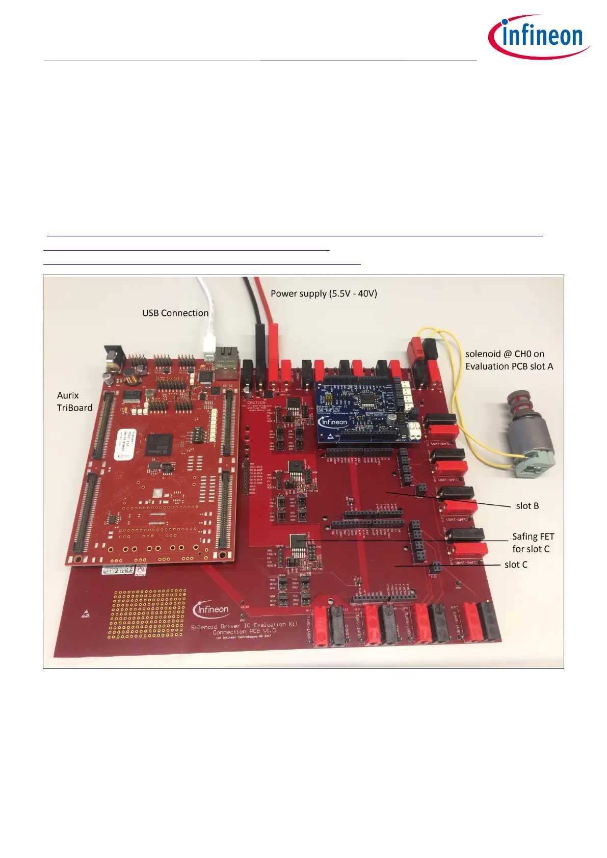
In Figure 10 a Version L setup with one Eval PCB and a TC277 microcotroller TriBoard is shown. The main
voltage input is connected to the upper middle connectors and supplies the whole board setup inclusive loads.
Take care on maximum current ratings. In case of using Eval PCBs in parallel supply the board via all four
supply connectors (two red, two black). Each Eval PCB slot has its own SPI chip select signal to support an
individual communication. The slots are named alphabetic. In Figure 10 a solenoid is connected to Channel 0 at
slot A of the connection PCB. If the TC277 microcontroller is flashed with the Commando Interpreter software
the TLE92464ED can be controlled via the USB connection by the PC. The USB connector can also be used to
falsh and debug own embedded software. It is recommended to use the TriCore Entry Toolchain
(https://www.infineon.com/cms/de/product/microcontroller/32-bit-tricore-tm-microcontroller/tricore-tm-
development-tools-software-and-kits/free-tricore-entry-tool-
chain/channel.html?channel=db3a304344134c7a014420d628fa76ec).
Figure 10 Setup example for Version L with a TC277 TriBoard
1.5 Schematics
This chapter contains the schematics of the Evaluation PCBs and the Connection PCB.