Install Arudino IDE
Install Infineon´s XMC Microcontroller Boards for Ardunio: https://github.com/Infineon/XMC-for-Arduino
Create your own SW Project
Compile the project (Sketch -> Verify/Compile)
Connect the XMC1100 Boot kit/XMC4700 Relax Kit via USB and upload the compiled project (Sketch ->
Upload)
2.4 Graphical User Interface (GUI)
The GUI can be use either with an XMC or TriBoard (incl. Connection PCB) setup. Both setups require a
microcontroller software for the communication with the GUI. The steps to flash the used microcontroller with
the firmware is explained in the previous sections.
Following steps should be taken to start before starting the GUI (see also “getting started”):
XMC: Plug a 12V supply into VBAT_EXT and GND and connect the XMC board via the USB connector to the
computer (see Figure 8)
TriBoard:
o Please install the DAS tool (see 2.1)
o Plug a 12V supply into the VBAT_EXT and GND Connectors on the Connection PCB and connect
the TriBoard via the USB connector with your computer (see Figure 10)
Start the GUI and connect to the right COM Port
When setting the EN Checkbox the EN-LED on the Eval PCB should glow and the communication to the
Solenoid Driver IC is fully operational.
2.4.1 Main Window
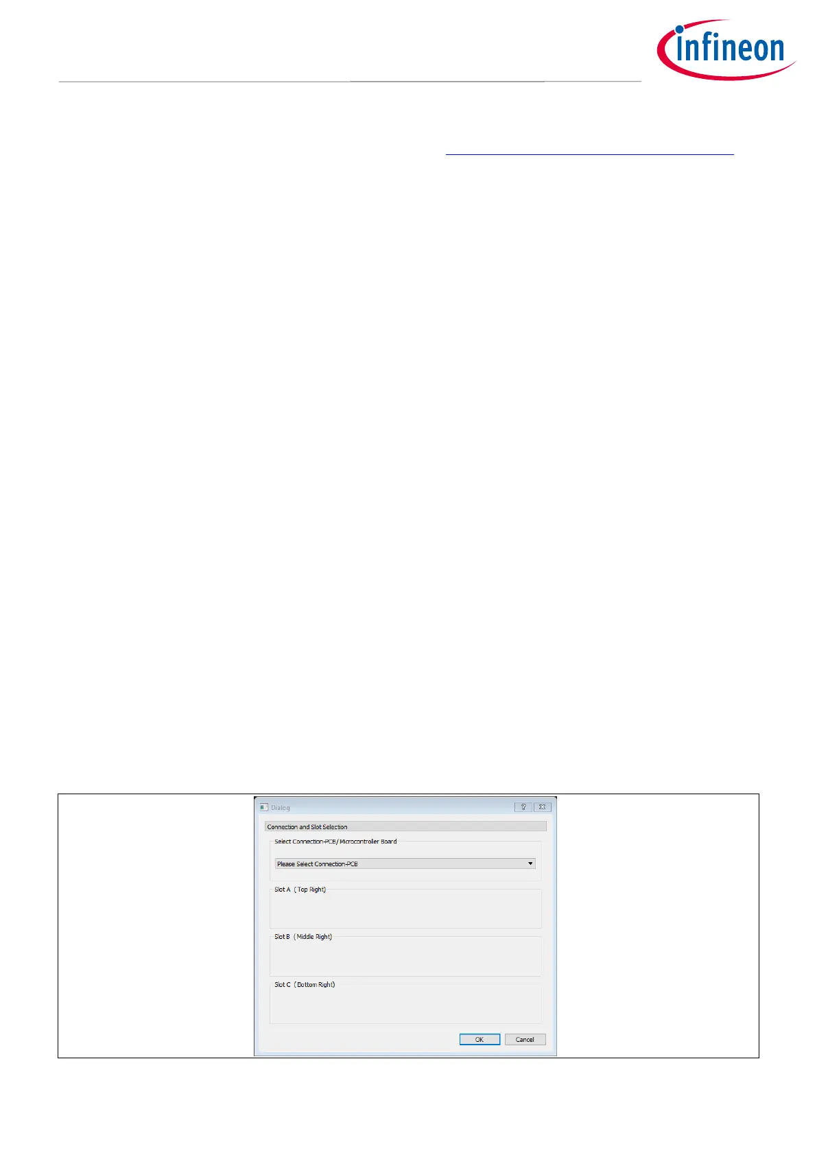
After starting the GUI a dialog window will pop up (Figure 24). From the first drop-down menu, select the
connection PCB or the microcontroller board (XMC1100 or XMC4700) which is being used to interface with the
evaluation board. Based on the first selection of either a common connection PCB or XMC microcontroller
board, it is possible to test either three or one evaluation board respectively. If the common connection PCB
was first chosen, the three IC evaluation boards being used should be selected for each slot from the three
subsequent drop-down menus. Alternatively, if a XMC is the tool of choice, then the user can only an evaluation
kit for Slot A in the dialog window shown in Figure 24.