Evaluation Board
User’s Manual 11 Rev. 1.2, 2013-06-06
Software Description for Evaluation Kits
3 Evaluation Board
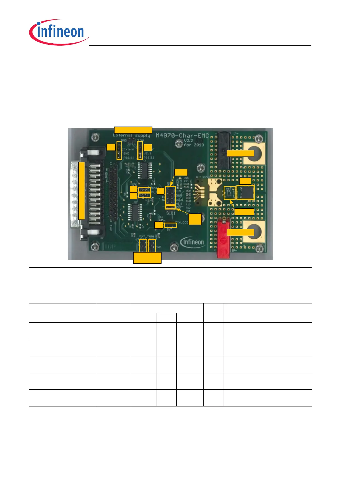
The Evaluation Board, see Figure 8, acts as an interface between one TLI4970 and one PGSISI-2. The objective
of the Evaluation Board is to electrically connect the sensor with the 25 pin D-Sub (DB25) connector of the PGSISI-
2.
The following chapter describes the functionality of the hardware. The layout and the schematic of the Evaluation
Board are shown in Figure 9 and Figure 10 respectively.
Figure 8 Evaluation Board for TLI4970
Table 2 Absolute maximum ratings
1)
1) General conditions (unless otherwise specified): V
DD
= 5.0 V; T
A
= 25 °C
Parameter Symbol Values Unit Note / Test Condition
Min. Typ. Max.
Supply voltage on
“External supply” pins
V
DD
-0.3 - +5.5 V
Maximum primary current
in socket
I
P_Socket
-10 - +10 A Sensor mounted inside the socket
Maximum primary current
for soldered device
I
P_PCB
-50 - +50 A Sensor soldered to PCB and no
sensor inside the socket
Maximum isolation
voltage
U
ISO
50 V Voltage between current rail and
measurement GND
Maximum ambient
temperature
T
A_Max
+60 °C
DUT
External supply
SPI
OCD
(SICI)
J4
J8
JP4
JP6
External trigger
inputs
DB25 (Interface to PGSISI-2)
J10
R16 - R19
Current input
Current output
JP1
 Loading...


