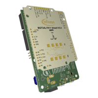
Using Infineon’s radar baseboard XMC4700 and BGT24LTR11 radar
shield with Arduino
Set-up guide
float getDopplerSensitivity(void);
Retrieve threshold that will determine motion with
direction (departing/approaching) or not
uint8_t setFramePeriod(uint8_t periodUs);
uint8_t getFramePeriod(void);
Retrieve configured frame period in µs
uint8_t setSampleFreq(uint32_t frequencyHz);
Set ADC sampling frequency in Hz
uint32_t getSampleFreq(void);
Retrieve ADC sampling frequency in Hz
uint8_t setSkipSamples(uint32_t numSamples);
Set the number of samples to skip at beginning of
frame
uint32_t getSkipSamples(void);
Retrieve the number of samples to skip at beginning
of frame
uint8_t setNumSamples(uint32_t numSamples);
Set size of raw IQ ADC buffer
uint32_t getNumSamples(void);
Retrieve configured size of raw IQ ADC buffer
uint8_t setPulseWidth(uint32_t widthUs);
Set the pulse width in µs
uint32_t getPulseWidth(void);
Retrieve the configured pulse width in µs
uint32_t getMinFramePeriod(void);
Get the minimum frame period in µs
4. Next, define the callback function to perform application tasks upon completion of a round of radar
processing, for example to turn on or off an LED. In the example shown in Figure 14, different LED colors are
used to indicate different radar processing results. Table 2 lists the APIs that can be called to retrieve the
result of the radar processing.
Table 2 Result APIs
bool targetAvailable(void);
Returns true: motion (with no direction), false: no
motion
float getDopplerLevel(void);
Retrieve the Doppler level of the detected target
float getDopplerFreqHz(void);
Retrieve the Doppler frequency of the detected
target
Retrieve the signed velocity value
uint8_t getDirection(void);
Returns 0: no direction, 1: departing, 2: approaching
Retrieve the unsigned speed value

 Loading...