Pin 1: UPS on Bypass mode.
Pin 2: Utility Normal (Normal close contact)
Pin 3: Utility Normal (Normal open contact)
Pin 4: Inverter On
Pin 5: Battery Low
Pin 6: Battery Bad or Abnormal
Pin 7: UPS Alarm
Pin 8: Common
Pin 9: Shutdown UPS positive(+ ) signal
Pin 10: Shutdown UPS positive(- ) signal
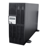
6.5.2 The shutdown function will be activated, after a +6~+25Vdc is put between
pin9 and pin10 for 5 seconds.
6.5.3 The capacity of each relay contact is 40Vdc/25mA.
6.5.4 Installation Position: slot1(CHA-CN7) or slot 2(CHB-CN8).
6.5.5 Flexible signal output for N.C.(Normal close) or N.O.(Normal open) contact by
shorting pin1-2 or pin2-3 from JP1-5.
6.5.6 The shutdown function will be enabled in 1 minute after blackout occurs if the
pin1-2 of both CN1 and CN6 be shorted by cap. Or, the shutdown function
can only be enabled by pin9-10 of CN3 if the pin2-3 of both CN1and CN6 be
shorted by cap. (Refer to 6.5.2)
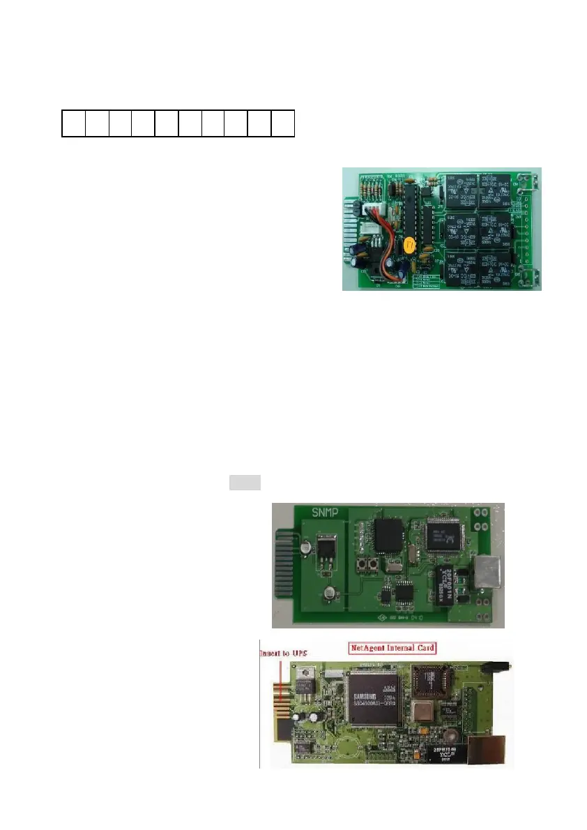
6.6. SNMP Cards
6.6.1 SNMP/WEB card
6.6.1.1 For installation, please
refer to the user’s manual
attached with the card. .
6.6.1.2 Position: slot 2(CHB).
6.6.2 Net Agent II Internal Card
6.6.2.1 For installation, please
refer to the user’s manual
attached with the card.
6.6.2.2 Position: slot 2(CHB).