INFOSEC UPS SYSTEM – 4 rue de la Rigotière – 44700 Orvault – France – www.infosec-ups.com
Hot Line Tel : +33 (0)2 40 76 15 82 – fax : +33(0)2 40 94 29 51 – hotline@infosec.fr – 04 09 AA XX 201 19
18
3.5.4 UPS Default Data and Special Function Execution
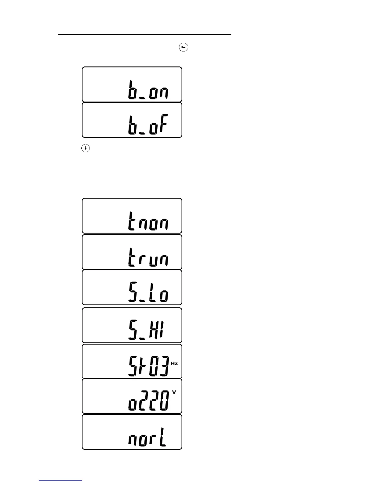
1. After UPS completely starts up, press key pad to change the LCD display screen to
drawing Q1.
Q1
* It shows buzzer “On”.
Q2
* It shows buzzer “Off”.
2. Press key pad to scroll down the screen and check the UPS settings. The LCD
display will show in consequence between Drawing Q1(buzzer) Drawing R1(Self-test)
Drawing S1(Bypass Voltage Windows) Drawing T(Output Frequency
Synchronization Window) Drawing U(Inverter Output Voltage) Drawing V1(UPS
Operation Mode) Drawing W(Output Voltage Micro Tune Value) Drawing X(UPS Id)
Drawing Y(Parallel function status).
R1
* It shows self-test is NOT “on”.
R2
* It shows self-test is “On”.
S1
* It shows Bypass Voltage is adjusted to narrow one.
S2
* It shows bypass voltage is adjusted to wider one.
T
* It shows Frequency Window is +/-3Hz.
U
* It shows inverter output voltage.
V1
* It shows the UPS is operated in “normal mode”.
 Loading...