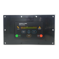
Diagnostics: XPM Expansion Module C:5-8
o only available when applicable EXP Expansion Box
is installed and registered (detected) by the X8I.
X8I Controller Diagnostics:
D1 Digital Input 1
D2 Digital Input 2 ON
D3 Digital Input 3
D4 Digital Input 4
D5 Digital Input 5 OFF
D6 Digital Input 6 Pulsing
D7 Digital Input 7
D8 Digital Input 8
-------------------------------------------------------------
R1 Relay Output 1
R2 Relay Output 2
R3 Relay Output 3 OFF
R4 Relay Output 4
R5 Relay Output 5 ON
R6 Relay Output 6
----------------------------------------------------------
Ao Analog Output 0.0 to 20.0mA
Digital Inputs:
OFF (open circuit)
ON (closed circuit)
Pulsing
Relay Outputs:
Each relay output can be energized and de-energized
manually by selecting the item. Use Up(plus) and
Down(minus) to adjust and Enter.
Ao: Analog Output:
The analog output can be manually adjusted. Press
Up(plus) and Down(Minus) to adjust and Enter. The
output will return to normal operational value upon
menu exit.
The analog output is utilized on the Terminal PCB to
switch the ir-PCB V outputs. Set the analog output to the
following to switch each ‘V’ output as required.
4.0mA All ‘V’ outputs OFF
7.0mA V1 = ON; V2, 3 and 4 = OFF
11.0mA V2 = ON; V1, 3 and 4 = OFF
15.0mA V3 = ON; V1, 2 and 4 = OFF
19.0mA V4 = ON; V1, 2 and 3 = OFF

 Loading...

