14 Installation
Telephone communicator
For SmartLine control panels it is necessary to enable the “Output to fault warning
routing equipment” option using SmartLeague software, above version 3.5.1.6.
PROGRAMMING
OPTIONS
•Polarity:
- Normally Open (default)
-Normally Closed
•Supervision:
- Enable (default)
-Disabled
• Programmable thresholds
EN54The “ALARM CALL” terminal is an E function input for the signalling of alarms.
The “FAULT CALL” terminal is a J function input for the signalling of faults.
If you desire to maintain an EN54-21 standard compliant system, DO NOT disable
terminal supervision.
The voltage applied to the “ALARM CALL” and “FAULT CALL” terminals must be
between 0 to 3.3V=.
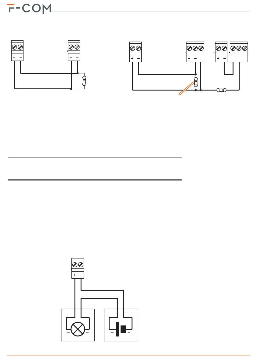
3-6-2Connecting ALARM ACK, FAULT
and OUT1 terminals
The three outputs, “ALARM ACK”, “FAULT” and “OUT1” are open-collector outputs
capable of driving maximum 150mA / 30V=.
The following wiring diagram illustrates connections for the activation of a load
when an output closes to ground.
FAULT
CALL
RELAY
NONC
C
ZONE 4
I/O
AUX R
1500Ohm
brown,
green, red
100Ohm
brown, black,
brown
SmartLine
F-COM
ALARM
CALL
DIALER
SmartLine
F-COM
3900Ohm
orange,
white, red
OUTPUT
Load
External
power
supply 30V=
max