Installation 13
Installation and User manual
3-5Connecting to a PC
It is necessary to connect to a PC equipped with the F-COM-STUDIO software for
the programming, layout and monitoring of the system the F-COM is connected to.
The connection with the PC can be achieved through a USB cable inserted into the
appropriate connector on the main board (table 1, D).
Once the F-COM is connected, the driver for the installation of the USB device
recognized by the PC is available in the F-COM-STUDIO software installation
folder, specifically in the following folder (in the case of a default installation):
C:\Program Files\F-COM-STUDIO\drivers\
3-6Connecting the terminals
EN54For the connection of the input/output terminals use:
Use shielded cable with the necessary number of conductors
Proper section (minimum 0.5mm², maximum 2.5 mm²)
Compliant with local standards and laws in force
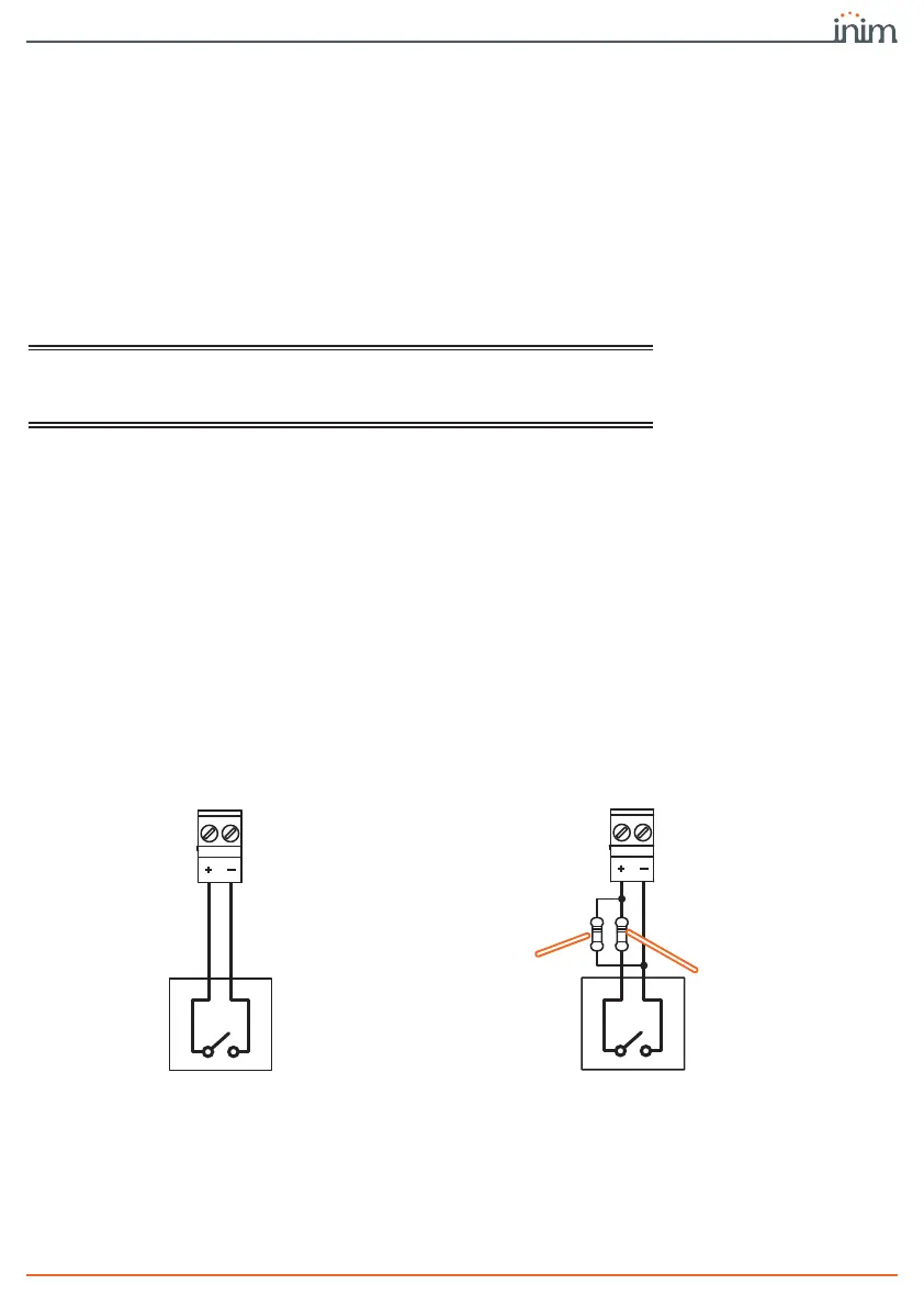
3-6-1ALARM CALL and FAULT CALL
connection
The “ALARM CALL” and “FAULT CALL” inputs are to be used for the start
communication signals relating to fire alarms and control panel faults.
These inputs can be supervised by connecting the appropriate balancing
resistance, and are compatible with the communicator output on Inim fire
detection panels.
The illustrated resistance values (3900 and 100Ohm) are those required when the
default input threshold values are used.
Since thresholds are programmable via the software, the installer can choose the
balancing resistance values.
When supervision is enabled, the occurrence of open and short-circuit conditions
will generate an “Interconnection fault”.
Following is the connection of the communicator with a SmartLine fire-detection
control panel manufactured by Inim Electronics, for alarm and fault
communications:
INPUT
3900Ohm
orange,
white, red
100Ohm
brown,
black, brown
ALARM/FAULT CALL
supervised
INPUT
ALARM/FAULT CALL
non-supervised