Using the communicator 21
Installation and User manual
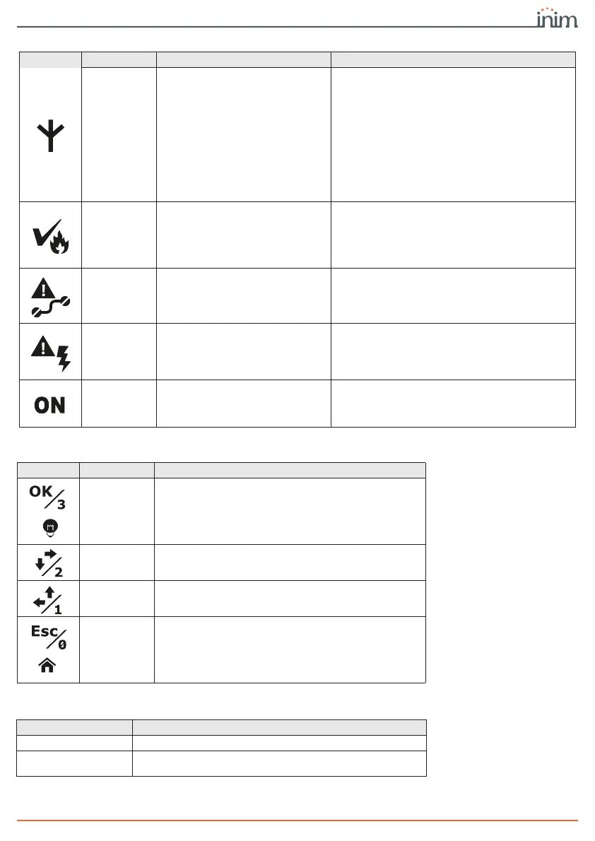
Mobile net-
work
Indicates that the communicator is
engaged in a call on the mobile
network or the presence of a mobile
network fault.
- Flashing green, indicates an ongoing
communication on the GSM network, different
from an alarm communication.
- Flashing red, indicates an ongoing alarm
communication on the GSM network.
- Solid yellow, indicates a fault on the mobile
network:
-Not registered to the network
-No SIM
-Insufficient signal
-Data network connection fault
-Insufficient credit
ACK alarm
Indicates receipt or not of the
confirmation of receipt of a fire
alarm communication or a voice
message.
- Solid red, indicates that an alarm
communication has received confirmation of
receipt.
- Solid yellow, indicates that an alarm
communication has not received confirmation
of receipt.
Interconnec-
tion fault
Indicates a fault in the connections
with the control panel or a fault
during supervision of phone
contacts.
- Solid yellow, indicates a fault detected during
supervision of the connection terminals
(ALARM CALL, FAULT CALL, ALARM ACK,
OUT1, FAULT, IO1, IO2, IO3) or telephone
contacts.
Power-sup-
ply fault
Signals power-supply faults and the
“System restart” event.
- Flashing yellow, in the event of one or more
faults detected by the power supply.
- Flashing yellow, indicates that system restart
has occurred. This signal has priority over the
other.
ON
Indicates that the communicator is
On.
- Solid green, communicator functioning.
Table 8: Signalling LEDs
Icon description activation signal
Table 9: Interface buttons
Icon description function
OK
- Access sub-menus
- Confirm entered data
- If pressed on the PIN entry template, enter “3”
- If pressed and held (for over 1 second), it accesses
the LED test
Right / Down
- Navigation menu
- If pressed on the PIN entry template, enter “2”
Left / Up
- Navigation menu
- If pressed on the PIN entry template, enter “1”
Esc
- Exit the sub-menus
- Cancel the data entering
- If pressed on the PIN entry template, enter “0”
- Pressing and holding (for over 1 second) steps back
to the main menu
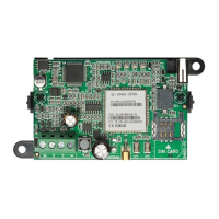
Table 10: Buttons on the main board
description function
RESET
Forces the communicator to restart.
FACTORY
Pressing for more than 5 seconds forces restoral of the
programming options.