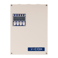
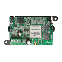
8 Device description
Telephone communicator
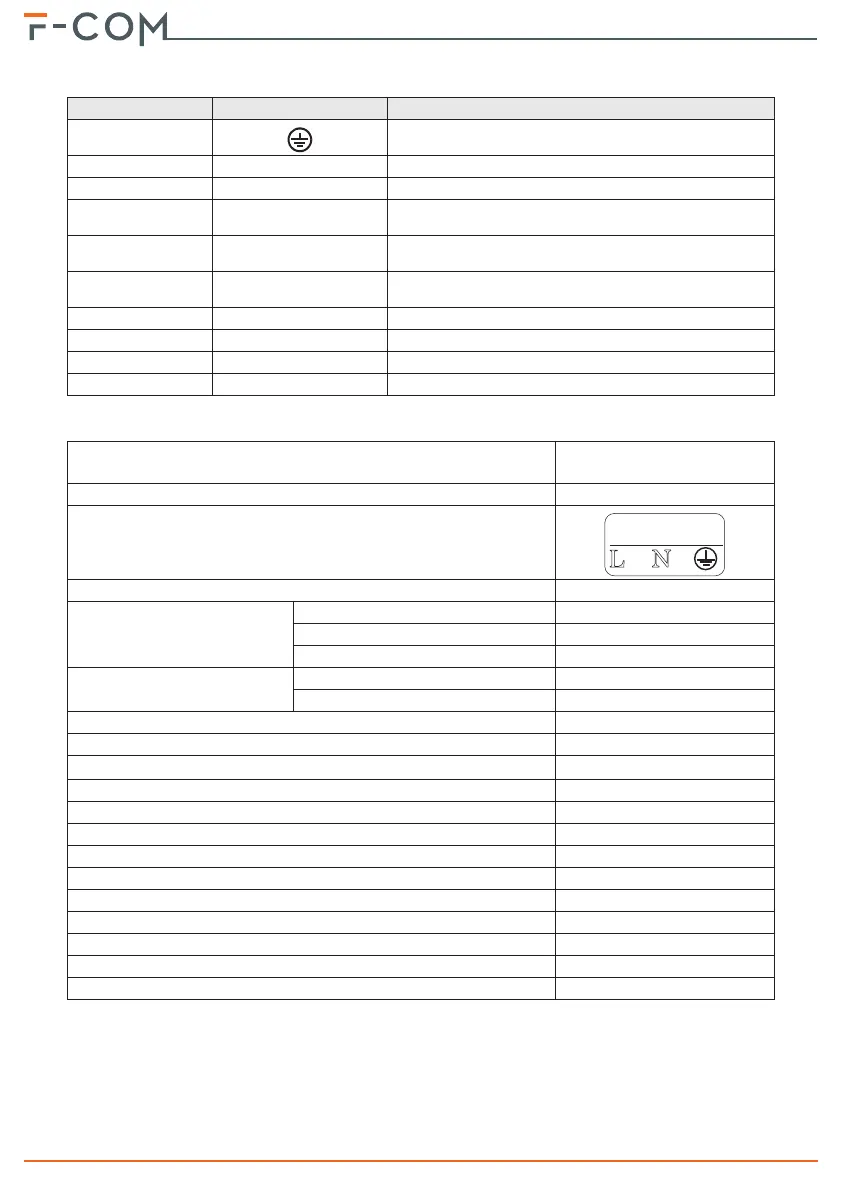
Table 2: Terminal board
n. icon/identifier function
1
Ground terminal
2, 3 L.E.
Telephone line connection terminals
4, 5 L.I.
Internal telephone line terminals
6ALARM ACK
Output terminal for confirmation of receipt of an alarm
communication
7OUT1
Programmable output terminal (by default it activates in
the event of a connection fault)
8FAULT
Output terminal that activates in the presence of
communicator faults
9, 13 -
Ground reference
10, 11, 12 IOx
Programmable input/output terminals
14, 15 ALARM CALL
Input terminal for the activation of alarm communications
16, 17 FAULT CALL
Input terminal for the activation of fault communications
Table 3: Technical specifications
Supply voltage
230V~ (-15% + +10%)
50/60Hz
Maximum absorption from the 230V line
0.5A
AC mains input terminals
Nominal output voltage
27.6V
Maximum current supplied by
the power-supply module
total
2.1A
for battery charging
0.6A
for external loads and main board
1.5A
Main board current absorption
during standby
50mA
during alarm
150mA
Battery specifications
2 x 12V / 1.3Ah
Minimum flammability class of casing
UL94-V2
Maximum internal resistance of battery (R
i max
)
2.7Ohm
Output voltage
19 / 27.6V
Battery shutdown tension
19V
Internal fuse of power supply module
T 3.15A 250V
Maximum output current ripple
1%
Operating temperature
from -5°C to 40°C
Insulation class
I
Enclosure protection class (EN 60529)
IP30
Classification in accordance with EN 54-21
Type 2
Dimensions (H x W x D)
260 x 200 x 55mm
Weight (without batteries)
1500g