16 Technical description
Conventional fire detection control panel
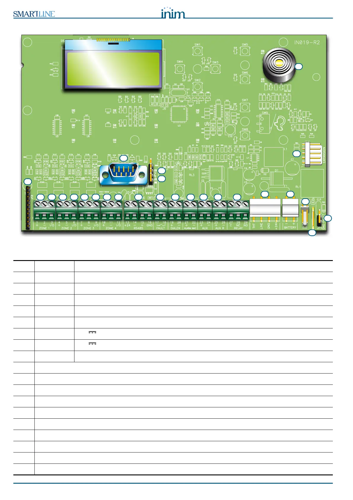
4.2 Internal devices
Figure 6 - SmartLine motherboard
Main components:
[A]
ZONE +
/
-
Zone detection-line terminals
[B]
ZONE I/O
Zone I/O terminals
[C]
RS485
RS485 BUS terminals for repeater and power station connections, max. 0.9 A
[D]
FAULT
Fault output, dry contact
[E]
DIALER
Output terminal for dialler connection, supervised
[F]
ALARM NAC
Supervised alarm output
[G]
AUX
24V - 0.8A output for external loads
[H]
AUX R
24V - 0.8A output for external loads - off during reset
[I]
RELAY
Programmable dry contact (Alarm at default)
[J]
Power-supply module connector
[K]
Connector for the earth wire of the power supply module
[L]
Earth-fault-bypass jumper - if this jumper is removed faults will be bypassed
[M]
RS232 serial port for PC connection
[N]
Jumper for programming from panel (keypad and LCD) J8
[O]
Jumper for programming from PC J9
[P]
Extinguishant module connector
[Q]
Buzzer
[R]
Connector for expansion board
[S]
Reserved connectors DO NOT USE
A B C D E F G H I
Q
A B A B A B
L
R
M
K
J
O
P
N
S
S