Home
Innodisk
Control Unit
E2SS-32R2
Page 18 (Quick Installation Guide)
Innodisk E2SS-32R2 - Quick Installation Guide; Component and Screw Identification
29 pages
Manual
Save Page as PDF
To Next Page
To Next Page
To Previous Page
To Previous Page
Loading...
E2SS
-
32R
2
15
R
e
v
1
.
0
T
P
S
,
A
u
g
2
0
23
Quick Installation G
uide
T
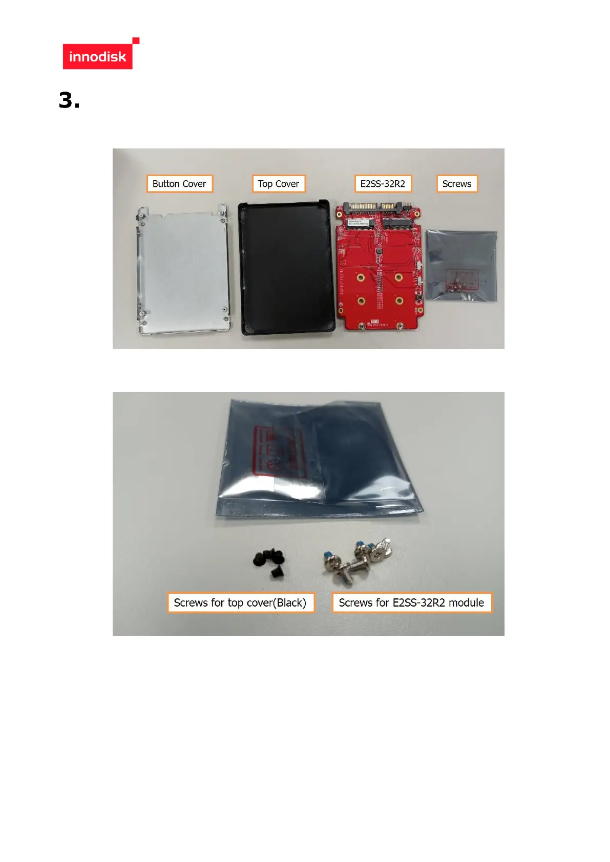
o instal
l the M.2 storage, the
followi
ng steps are requi
red.
Check the component
for button cove
r
, top c
over
, E2SS
-
32R2,
screws.
Check the screws fo
r each part.
17
19
Table of Contents
Main Page
Default Chapter
2
Table of Contents
2
Table of Contents
3
Revision History
3
List of Tables
4
List of Figures
5
Figure 5: Mpcie Smd 2*26P Drawing
15
Packing List
17
Software Support
17
Quick Installation Guide
18
E2Ss Rebuild Disk Sop
21
Features
6
Figure 1: Block Diagram
6
Figure 2: E2Ss-32R2 Picture
6
Product Specifications
7
Overview
6
Product Introduction
6
Device Parameters
7
Electrical Specifications
7
Power Requirement
7
Power Consumption
7
Environmental Specifications
7
Temperature Ranges
7
Humidity
7
Shock and Vibration
8
Mean Time between Failure (Mtbf)
8
Ce and Fcc Compatibility
8
Rohs Compliance
8
Hardware
9
Layout
9
Pin Define
10
I/O Connector Mechanical Drawing
12
Figure 3: 7+15P Sata Connector Drawing
12
Figure 4: Pin Header 2*5P Drawing
13
Figure 6: Switch Smd 3P Drawing
15
E2Ss-32R1 Mechanical Drawing
16
Figure 7: E2Ss-32R2 Drawing
16
Raid Level Setting
17
Led Indicator
17
Contact Us
29
Related product manuals
Innodisk EMP2 SERIES
14 pages