CLS FUSION Montage- und Betriebsanleitung
CLS FUSION Mounting and Operating Instructions
24
6.3.4. Final circuits
The CLS FUSION System has 8 nal circuits (4 nal cir-
cuits at CLS FUSION-7 Ah) to each monitor 20 luminaire
addresses. The nal circuits can each carry a load of max.
3A with a 5A fuse. Please make sure the total load on the
entire system is not exceeded.
5. Technical data - page 11
Using low voltage (SELV) to supply the emergency light-
ing simplies cabling and eliminates the need for a PE
conductor. Please observe the wire lengths specied in
Appendix B. Wire lengths - Seite 96
The luminaires are connected at terminals + and -, of
which there are 2 per nal circuit. Each luminaire has a
unique ID which you must then assign to a local address
on the circuit when you program it.
8.4.5. Luminaire programming - page 51
When (un)installing the luminaires, make sure
the IDs on the casing and the module match.
In the event of replacement installation, make sure an
identical luminaire ID is not connected more than once
to a circuit of a CLS.
Max. wire length of nal circuits
Appendix B. Wire lengths - Seite 96
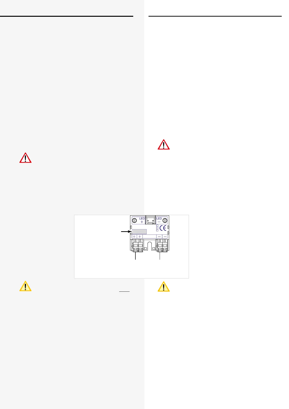
Connection example L-JET
If the lamp ID starts with a “0”, the number is not
displayed in the congurator and in the control
section.
6.3.4. Endstromkreise
Das CLS FUSION System besitzt bis zu 8 Endstromkreise
(bis zu 4 Endstromkreise bei CLS FUSION-7 Ah) zur Über-
wachung von je 20 Leuchtenadressen. Die Endstrom-
kreise können jeweils mit bis zu max. 3A belastet werden
und sind mit 5A abgesichert. Dabei ist aber auf die
Gesamtbelastung des ganzen Systems zu achten.
5. Technische Daten - Seite 11
Der Einsatz von Kleinspannung (SELV) zur Versorgung
der Notbeleuchtung vereinfacht die Verkabelung und
eine PE-Ader entfällt. Bitte beachten Sie dazu die Anga-
ben zur Leitungslänge im
Anhang B. Leitungslängen - Seite 96
Über die Klemmen + und -, die pro Endstromkreis dop-
pelt ausgeführt sind, werden die Leuchten angeschlos-
sen. Jede Leuchte besitzt eine eindeutige ID, die dann
bei der Programmierung einer lokalen Adresse im Strom-
kreis zugeordnet werden muss.
8.4.5. Leuchten Programmierung - Seite 51
Bei der De-/Montage der Leuchten ist darauf
zu achten, dass die IDs auf Gehäuse und Modul
übereinstimmen!
Im Fall einer Nachinstallation ist darauf zu achten, dass
jede Leuchten-ID pro Stromkreis nur einmal an der CLS
angeschlossen wird!
Max. Leitungslänge Endstromkreis
AnhangB. Leitungslängen - Seite 96
Anschlussbeispiel L-JET
Wenn die Leuchten-ID mit einer „0“ beginnt, wird
die Zahl im Kongurator und im Steuerteil nicht
angezeigt.
INOTEC
L-JET
860 02 1
3
7
ta: 50°C/U
n
:DC 24V±20%
Eingang
Endstromkreis
Final circuits
-
+
56738
Leuchten-ID
Luminaire ID
 Loading...