CLS FUSION Montage- und Betriebsanleitung
CLS FUSION Mounting and Operating Instructions
31
Bei der Stromschleife muss die Zenerabschluss-
klemme am letzten Dreiphasenüberwachungs-
modul in Reihe zum Schaltkontakt eingebaut
werden.
Besteht die Anforderung, dass weitere Geräte bei
Netzausfall einer Unterverteilung mit einschalten,
kann dies wie folgt realisiert werden. Dazu ist der
optionale Meldekontakt auf die Stromschleife des fol-
genden Gerätes zu verdrahten. Zur Überwachung der
Stromschleife auf Kurzschluss und Unterbrechung kön-
nen optional Zenerabschlussklemmen eingesetzt
werden.
Der optionale Kontakt ist als Öner mit Meldung
Netzausfall UV und Netzausfall HV zu programmieren
8.4.8.3. Menü RIF - Seite 62
Zur Hinterlegung von Zielortangaben und für die
Zuordnung von Schaltzuweisungen zu Leuchten
muss anstatt der DPÜ die busfähige Variante, die
DPÜ/B.2 ausgewählt werden.
L1
L2
L3
N
PE
sub db 1
L1
L2
L3
N
PE
sub db 2
L1
N
PE
sub db 3
UVA 1 UVA 2 UVA 3
L3 L1
L2 N
L1
DPÜ
L2
gem.
VDE
0108
L3
12
14 11
INOTEC
L3 L1
L2 N
L1
DPÜ
L2
gem.
VDE
0108
L3
12
14 11
INOTEC
L3 L1
L2 N
L1
DPÜ
L2
gem.
VDE
0108
L3
12
14 11
INOTEC
Allgemeinbeleuchtung Allgemeinbeleuchtung Allgemeinbeleuchtung
General lighting General lighting General lighting
SL- SL+
Letzte DPÜ
Zener-
abschluss
Artikel Nr. 999 003
Last DPÜ
Zener diode
termination
Art. no. 999 003
1 2 3 4 56 78 910 11 12 13 1415 16 17 18 19 20
Betrieb
Operation
Batt.-Betrieb
Batt.-Operation
Störung
Failure
Lade Störung
Charge Failure
SK 1
Ein
On
Störung
Failure
SK 2
Ein
On
Störung
Failure
SK 3
Ein
On
Störung
Failure
SK 4
Ein
On
Störung
Failure
CLS 24.1
1 2 3 4 56 78 910 11 12 13 1415 16 17 18 19 20
Betrieb
Operation
Batt.-Betrieb
Batt.-Operation
Störung
Failure
Lade Störung
Charge Failure
SK 1
Ein
On
Störung
Failure
SK 2
Ein
On
Störung
Failure
SK 3
Ein
On
Störung
Failure
SK 4
Ein
On
Störung
Failure
CLS 24.1
+24V
+–
Opt.
Stoer
Betr.
Bat.-B.
SL- SL+SL- SL+SL- SL+ SL- SL+
Optionaler Kontakt
Optional contact
CLS FUSION CLS FUSION
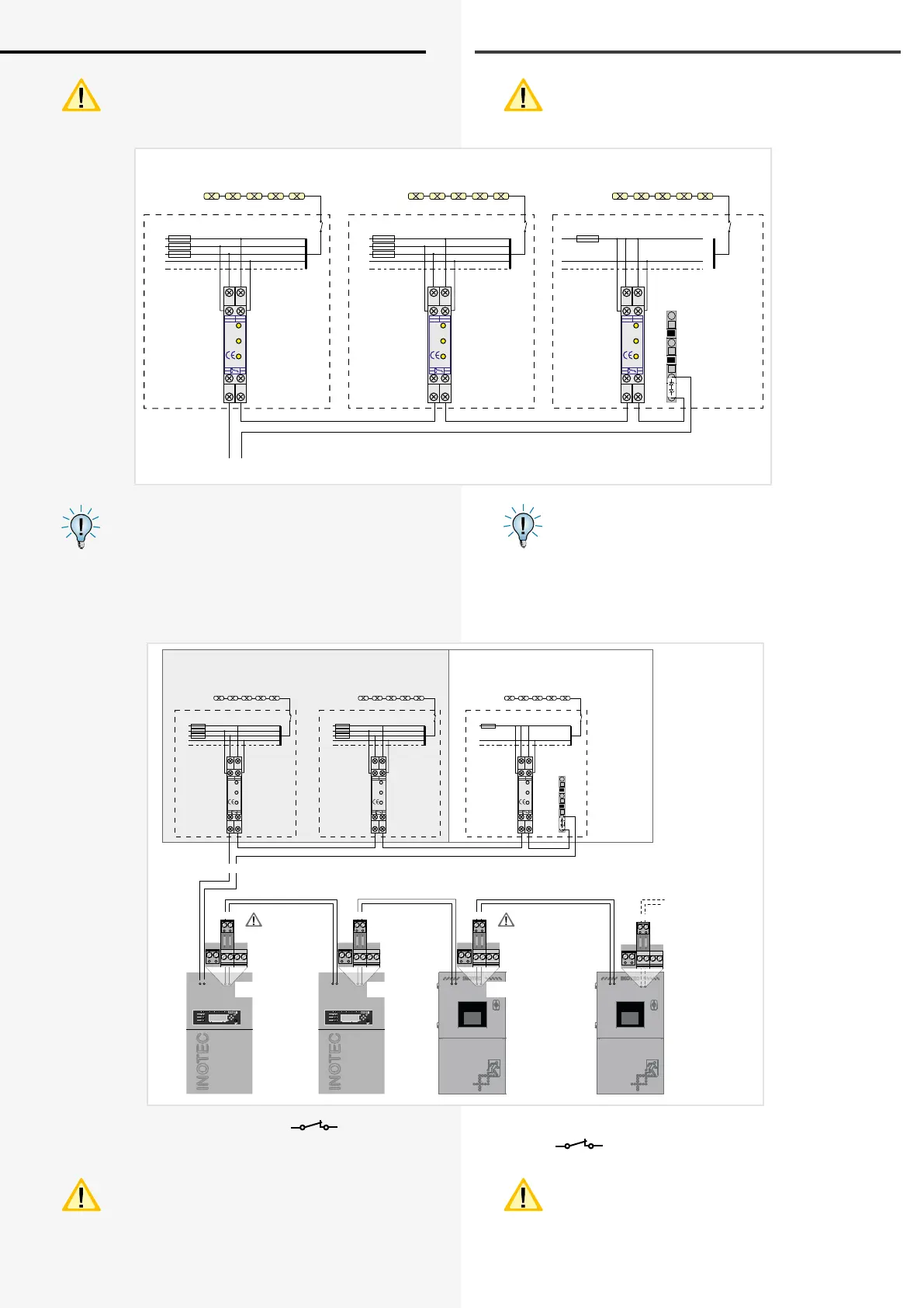
Anschluss bei Überwachung mit einphasigem Netz
Supply monitoring in single-phase installation.
L1
L2
L3
N
PE
UVA 1
L1
L2
L3
N
PE
UVA 2
L1
N
PE
UVA 3
L3 L1
L2 N
L1
DPÜ
L2
gem.
VDE
0108
L3
12
14 11
INOTEC
L3 L1
L2 N
L1
DPÜ
L2
gem.
VDE
0108
L3
12
14 11
INOTEC
L3 L1
L2 N
L1
DPÜ
L2
gem.
VDE
0108
L3
12
14 11
INOTEC
Allgemeinbeleuchtung Allgemeinbeleuchtung Allgemeinbeleuchtung
General lighting General lighting General lighting
Anschluss bei Überwachung mit dreiphasigem Netz
Supply monitoring in three-phase installation.
SL- SL+
Zenerdiode
für CLS FUSION
Artikel Nr. 999 014
Zener diode
termination
for CLS FUSION
Zenerdiode
für CLS 24.1
Artikel Nr. 999 010
Zener diode
termination
for CLS 24.1
Opt.
+24V
+–
Opt.
Stoer
Betr.
Bat.-B.
Opt.
+24V
+–
Opt.
Stoer
Betr.
Bat.-B.
Opt.
Optionaler Kontakt
Optional contact
Optionaler Kontakt
Optional contact
+24V
+–
Opt.
Stoer
Betr.
Bat.-B.
weitere CLS Anlagen
additional CLS systems
Opt.
Letzte DPÜ
Zener-
abschluss
Artikel Nr. 999 003
Last DPÜ
Zener diode
termination
Art.no. 999 003
With the current loop, the zener terminal must be
tted on the last three-phase monitoring module
in series to the switching contact.
If additional devices need to be switched on in
the event of a power failure to asub-distribution
board, this can be realised as follows. The optional
signalling contact must be wired to the current loop of
the subsequent device. Optionally a Zener diode can be
used to monitor the 24V current loop for open- or short
cicuit.
The optional contact has to be programmed as NC-
contact for the signal sub-db failure and mains
failure. 8.4.8.3. RIF menu - page 62
To deposit the destination information and for
allocating the switch allocation of the luminaires
the bus-capable version DPÜ/B.2 must be chosen
instead of the DPÜ.
 Loading...