CLS FUSION Montage- und Betriebsanleitung
CLS FUSION Mounting and Operating Instructions
96
B. Leitungslängen
• Endstromkreise
• RTG BUS
max. 500m min. 0,5mm²
• CAN Bus
max. 1000m min. 0,5mm²
Bei der Angabe der Leitungslänge handelt es sich
um die max. Gesamtlänge. Diese beinhaltet alle
Leitungsstränge incl. Stiche
C. Kundendienst
Bevor Sie den Kundendienst beauftragen, überprüfen
Sie bitte folgendes:
• Prüfung auf Leuchtenfehler:
• Starten Sie einen Funktionstest
Im Reparaturfall oder wenn die Fehler immer noch
anstehen, so wenden Sie sich bitte an Ihre zuständige
Vertretung und geben die folgende Informationen mit
an:
• Projektname
• Gerätetyp und Gerätenummer (KA……) vom
Typenschild
• Eine kurze Beschreibung der Störung
• Klartextinformation im Steuerteil
ablesbar, klick auf den Statusbalken
• Softwareversion, zu nden unter
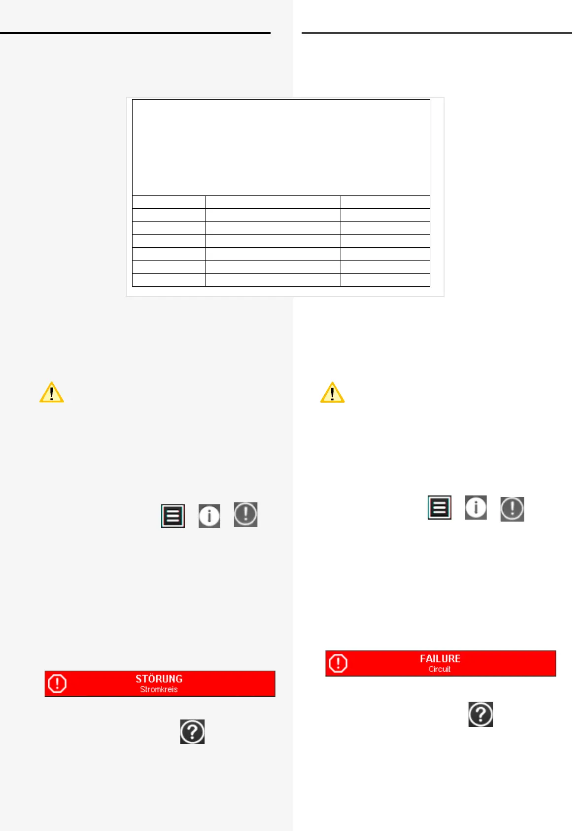
Max. Spannungsfall auf der Leitung = 3,5V !!!
Absicherung je Stromkreis: 5A
Max. Belastung je Stromkreis: 3A
Max. Leitungslängen bei max. Spannungsfall von 3,5V
Max. voltage drop on cable = 3,5V !!!
Fuse protection per nal circuit: 5A)
Max. load per nal circuit: 3A
Max. wire lengths for max. voltage drop of 3,5V:
Strom / Load Querschnitt / Cross section Länge / Length
3A 1,5 mm² 49m
2A 1,5 mm² 74m
1A 1,5 mm² 147m
3A 2,5 mm² 82m
2A 2,5 mm² 123m
1A 2,5 mm² 245m
B. Wire lengths
• nal circuits
• RTG BUS
max. 500m min. 0,5mm²
• CAN Bus
max. 1000m min. 0,5mm²
The max. wire length is the total length of one
circuit incl. all stubs.
C. Customer service
Before contacting the customer service, please test the
following:
• Test on luminaire failure:
• Start a function test
In the repair case or if the failures still occur, please
contact the representative and transfer the following
information:
• Project name
• Device type and device number (KA…..) at the type
plate
• Short description of the failure
• Plain text information readable at
the controller, click on the status bar
• Software version, accessible under
 Loading...