MD380 User Manual Desc
ription of Function Codes
- 159 -
Set the over-excitation gain to 0 in the applications where the inertia is small and the bus
voltage will not rise during motor deceleration or where there is a braking resistor.
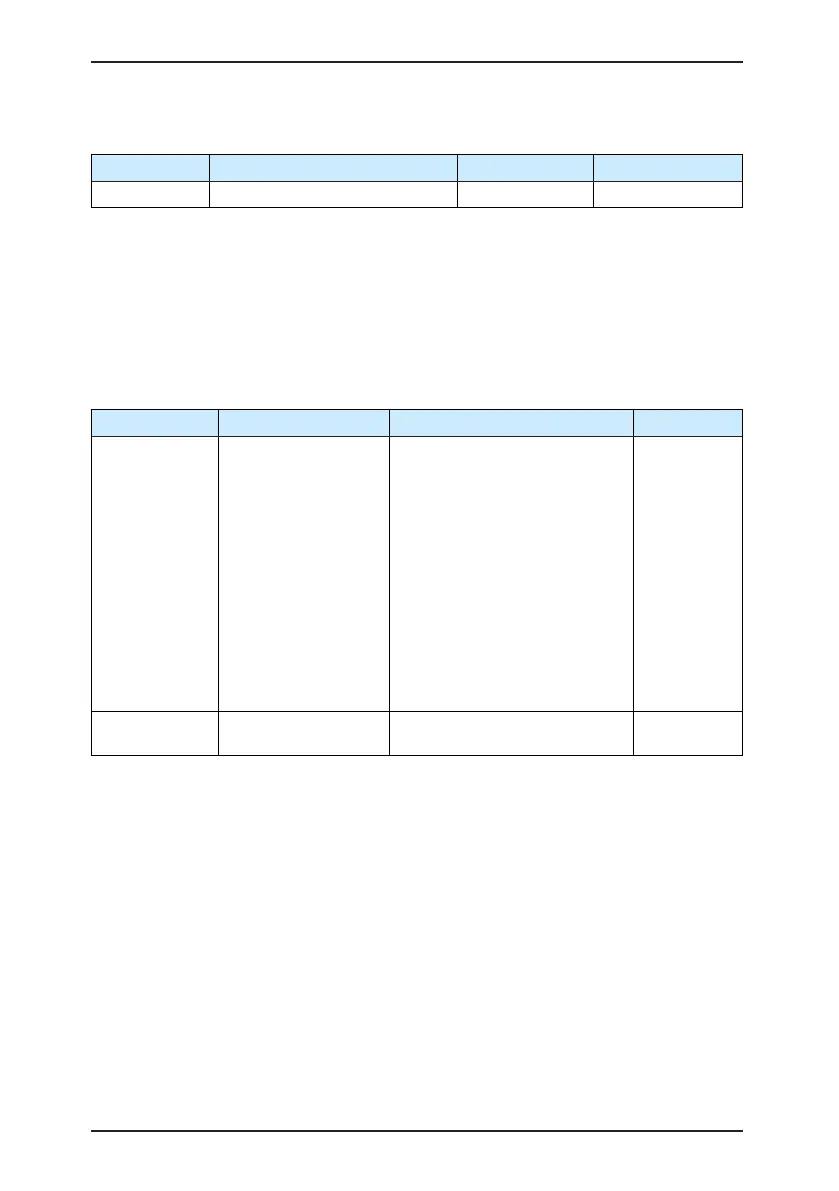
Function Code Parameter Name Setting Range Default
F3-11 V/F oscillation suppression gain 0–100 Model dependent
Set this parameter to a value as small as possible in the prerequisite of efcient oscillation
suppression to avoid inuence on V/F control.
Set this parameter to 0 if the motor has no oscillation. Increase the value properly only
when the motor has obvious oscillation. The larger the value is, the better the oscillation
suppression result will be.
When the oscillation suppression function is enabled, the rated motor current and no-
load current must be correct. Otherwise, the V/F oscillation suppression effect will not be
satisfactory.
Function Code Parameter Name Setting Range Default
F3-13
Voltage source for V/F
separation
0: Digital setting (F3-14)
1: AI1
2: AI2
3: AI3
4: Pulse setting (DI5)
5: Multi-reference
6: Simple PLC
7: PID
8: Communication setting
100.0% corresponds to the rated
motor voltage (F1-02, A4-02, A5-
02, A6-02).
0
F3-14
Voltage digital setting
for V/F separation
0 V to rated motor voltage 0 V
V/F separation is generally applicable to scenarios such as induction heating, inverse power
supply and motor torque control.
If V/F separated control is enabled, the output voltage can be set in F3-14 or by means of
analog, multi-reference, simple PLC, PID or communication. If you set the output voltage by
means of non-digital setting, 100% of the setting corresponds to the rated motor voltage. If a
negative percentage is set, its absolute value is used as the effective value.
• 0: Digital setting (F3-14)
The output voltage is set directly in F3-14.
• 1: AI1; 2: AI2; 3: AI3
The output voltage is set by AI terminals.
• 4: Pulse setting (DI5)
The output voltage is set by pulses of the terminal DI5.

 Loading...
