MD380 User Manual Desc
ription of Function Codes
- 165 -
If the frequency source is multi-reference, the value 100% of FC-00 to FC-15 corresponds to
the value of F0-10 (Maximum frequency).
Besides the multi-speed function, the multi-reference can be also used as the PID setting
source or the voltage source for V/F separation, satisfying the requirement on switchover of
different setting values.
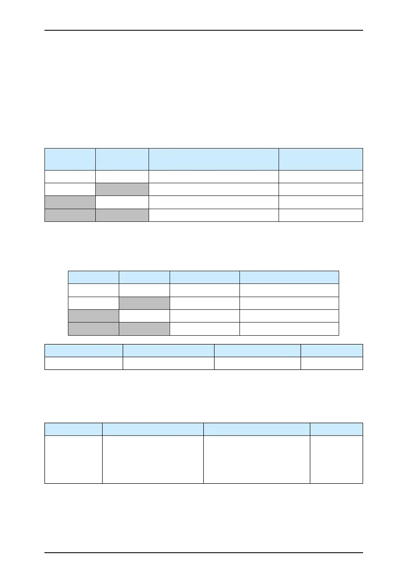
Two terminals for acceleration/deceleration time selection have four state combinations, as
listed in the following table.
Table 6-3 State combinations of two terminals for acceleration/deceleration time selection
Terminal 2 Terminal 1
Acceleration/Deceleration Time
Selection
Corresponding
Parameters
OFF OFF Acceleration/Deceleration time 1 F0-17, F0-18
OFF ON Acceleration/Deceleration time 2 F8-03, F8-04
ON OFF Acceleration/Deceleration time 3 F8-05, F8-06
ON ON Acceleration/Deceleration time 4 F8-07, F8-08
Two motor selection terminals have four state combinations, corresponding to four motors,
as listed in the following table.
Table 6-4 State combinations of two motor selection terminals
Terminal 2 Terminal 1 Selected Motor Corresponding Parameters
OFF OFF Motor 1 Group F1, Group F2
OFF ON Motor 2 Group A2
ON OFF Motor 3 Group A3
ON ON Motor 4 Group A4
Function Code Parameter Name Setting Range Default
F4-10 DI lter time 0.000–1.000s 0.010s
It is used to set the software filter time of DI terminal status. If DI terminals are liable to
interference and may cause malfunction, increase the value of this parameter to enhance
the anti-interference capability. However, increase of DI lter time will reduce the response
of DI terminals.
Function Code Parameter Name Setting Range Default
F4-11 Terminal command mode
0: Two-line mode 1
1: Two-line mode 2
2: Three-line mode 1
3: Three-line mode 2
0
This parameter is used to set the mode in which the AC drive is controlled by external
terminals. The following uses DI1, DI2 and DI3 among DI1 to DI10 as an example, with
allocating functions of DI1, DI2 and DI3 by setting F4-00 to F4-02.

 Loading...
