MD380 User Manual Desc
ription of Function Codes
- 235 -
Function Code Name Setting Range Default
A6-09
Corresponding setting of AI
curve 5 minimum input
-100.0%–100.0% 0.0%
A6-10 AI curve 5 inexion 1 input A6-08 to A6-12 3.00 V
A6-11
Corresponding setting of AI
curve 5 inexion 1 input
-100.0%–100.0% 30.0%
A6-12 AI curve 5 inexion 1 input A6-10 to A6-14 6.00 V
A6-13
Corresponding setting of AI
curve 5 inexion 1 input
-100.0%–100.0% 60.0%
A6-14 AI curve 5 maximum input A6-14 to 10.00 V 10.00 V
A6-15
Corresponding setting of AI
curve 5 maximum input
-100.0%–100.0% 100.0%
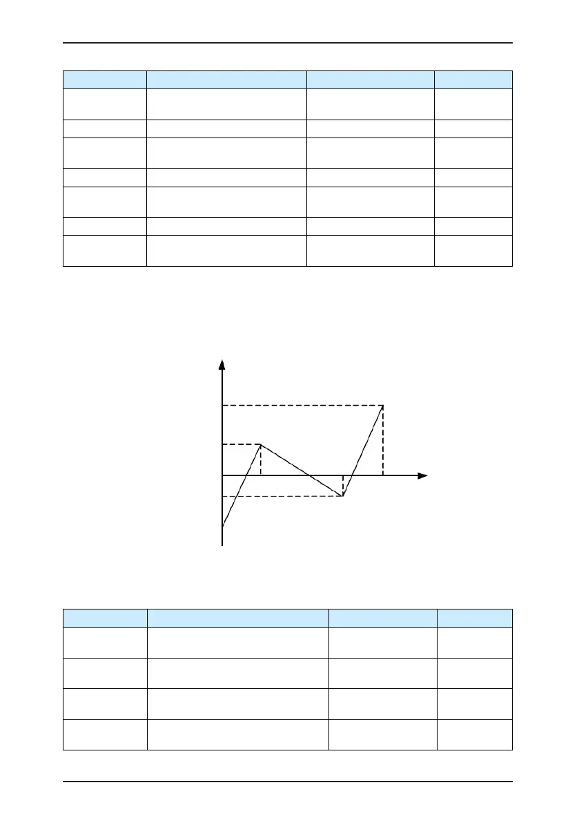
The function of curve 4 and curve 5 is similar to that curve 1 to curve 3, but curve 1 to
curve 3 are lines, and curve 4 and curve 5 are 4-point curves, implementing more exible
corresponding relationship. The schematic diagram of curve 4 and curve 5 is shown in the
following gure.
Figure 6-34 Schematic diagram curve 4 and curve 5
AI corresponding setting
Corresponding setting
of AI max. input
Corresponding setting of
AI curve inflexion 1 input
0 V (0 mA)
Corresponding setting of
AI curve inflexion 2 input
Corresponding setting
of AI min. input
AI curve
inflexion 1
AI curve
inflexion 2
AI input
voltage
10 V (20 mA)
When setting curve 4 and curve 5, note that the curve's minimum input voltage, inexion 1
voltage, inexion 2 voltage and maximum voltage must be in increment order.
F4-34 (AI curve selection) is used to select curve for AI1 to AI3.
Function Code Parameter Name Setting Range Default
A6-16
Jump point of AI1 input
corresponding setting
-100.0%–100.0% 0.0%
A6-17
Jump amplitude of AI1 input
corresponding setting
0.0%–100.0% 0.5%
A6-18
Jump point of AI2 input
corresponding setting
-100.0%–100.0% 0.0%
A6-19
Jump amplitude of AI2 input
corresponding setting
0.0%–100.0% 0.5%

 Loading...
