MD380 User Manual Desc
ription of Function Codes
- 229 -
Decided by A1-06
The VDI state is determined by the binary bit of A1-06. For example, to implement
the function that the AC drive automatically enters the running state after power-on,
perform the following setting:
1) $OORFDWH9',ZLWKIXQFWLRQ)RUZDUG581):'$
2) Set A1-05 to xxx1: The state of VDI1 is decided by A1-06.
3) Set A1-06 to xxx1: VDI1 is valid.
4) Set F0-02 to 1: The command source to terminal control.
5) Set F8-18 to 0: Startup protection is not enabled.
:KHQWKH$&GULYHFRPSOHWHVLQLWLDOL]DWLRQDIWHUSRZHURQLWGHWHFWVWKDW9',LVYDOLG
DQG9',LVDOORFDWHGZLWKWKHIXQFWLRQRIIRUZDUG5817KDWLVWKH$&GULYHUHFHLYHV
WKHIRUZDUG581FRPPDQGIURPWKHWHUPLQDO7KHUHIRUH7KH$&GULYHVWDUWVWRUXQLQ
forward direction.
Function Code Parameter Name Setting Range Default
A1-07 Function selection for AI1 used as DI 0–59 0
A1-08 Function selection for AI2 used as DI 0–59 0
A1-09 Function selection for AI3 used as DI 0–59 0
A1-10 State selection for AI used as DI
0: High level active
1: Low level active
000
8QLWVGLJLW$,
Ten's digit (AI2)
Hundred's digit (AI3)
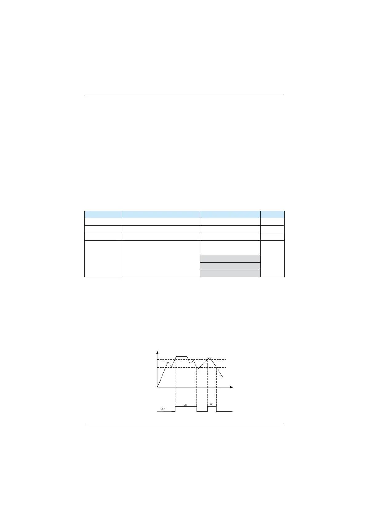
7KHIXQFWLRQVRIWKHVHSDUDPHWHUVDUHWRXVH$,DV',:KHQ$,LVXVHGDV',WKH$,VWDWH
is high level if the AI input voltage is 7 V or higher and is low level if the AI input voltage is 3
V or lower. The AI state is hysteresis if the AI input voltage is between 3 V and 7 V. A1-10 is
used to determine whether high level valid or low level valid when AI is used as DI.
The setting of AIs (used as DI) function is the same as that of DIs. For details, see the
descriptions of group F4.
The following figure takes AI input voltage as an example to describe the relationship
between AI input voltage and corresponding DI state.
Figure 6-34 Relationship of AI input voltage and corresponding DI status
Time
7 VDC
3 VDC
AI input
voltage
AI terminal state
efesotomasyon.com
 Loading...
