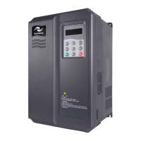
4 HCU Control Module
- 79 -
4.2 HCU Standard Terminals
Table 4-1 Description of standard terminals of the HCU control module
Name Mark Description
Input power
supply
XPWR: 24VI HCU power supply
Digital power
output
XDPWR: 24VD Digital output power isolated from XPWR
Digital input XDI: DI1–DI6, DIL Input type: relay contact, NPN or PNP
High-speed
digital input
XHDIO: HDI1, HDI2 Input type: NPN or PNP
High-speed
digital output
XHDIO: HDO1, HDO2 Output type: open collector
Analog output XAO: AO1, AO2
Output type: current or voltage, selected by
jumper
Analog input XAI: AI1, AI2
Input type: current or voltage, selected by
jumper
relay output XRO1, XRO2, XRO3 Relay output: NO, NC and COM
Inolink
communication
XCOMM
High speed RS485, bus resistor is selected by
jumper
RJ45 terminal X11, X12
For communication with the SOP-20-880 or
PC (requires RS485-RS232 converter). Both are
identical for multiple HCU cascade; connection
cable < 3 m
4.3 Dimensions and Installation Instructions
4.3.1 Installation Precautions
DANGER
◆
Before installing or removing the HCU, the cabinet must be powered o for
more than 15 minutes. The HCU input power must be disconnected to avoid
damage to the HCU control module caused by live installation or removal.
◆
When installing or removing a function module on the HCU, you must ensure
that the HCU input power is disconnected to avoid damage to the HCU or
function module caused by live installation or removal.
◆
Protect the HCU module from falling or impact to avoid damage to the
module.
◆
Do not disassemble the HCU module, otherwise the module may be
damaged.
◆
Do not use excessive torque to tighten the terminals to avoid damage.
■
Tool
1# Phillips screwdriver

 Loading...


