- 35 -
2 System Commissioning
2
2.2 System Commissioning
2.2.1 Safety Check Before Commissioning
The elevator needs to be commissioned after being installed; the correct commissioning guarantees safe
and normal running of the elevator. Before performing electric commissioning, check whether the electrical
part and mechanical part are ready for commissioning to ensure safety. At least two persons need to be
onsite during commissioning so that the power supply can be cut off immediately when an abnormality
occurs.
1. Check mechanical safety.
Check that the shaft is unobstructed, there is no person in the shaft, inside or on top of the car, and
the conditions for elevator safe running are met.
2. Check electrical wiring.
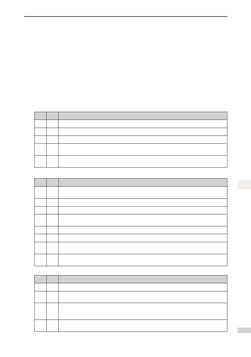
□√ No. Item
□ 1 The power supply R, S, T cables are wired correctly and securely.
□ 2 The UVW cables between the controller and the motor are wired correctly and securely.
□ 3 The controller (cabinet) and motor are grounded correctly.
□ 4
The safety circuit is conducted, and the emergency stop buttons and switches in the cabinet
and in the equipment room can be enabled.
□ 5
The door lock circuit is conducted. The door lock circuit is disconnected when the car door or
any hall door opens.
3. Check electrical safety.
□√ No. Item
□ 1
The line voltage of the user power supply is within 380 to 440 VAC, and the phase unbalance
degree does not exceed 3%.
□ 2 The total lead-in wire gauge and total switch capacity meet the requirements.
□ 3 There is no inter-phase or to-ground short circuit in the R, S, T power supply.
□ 4
There is no inter-phase or to-ground short circuit in the U, V, W phases of the controller. There
is no inter-phase or to-ground short circuit in the U, V, W phases of the motor.
□ 5 There is no short circuit to ground on the output side of the transformer.
□ 6 There is no inter-phase or to-ground short circuit in the 220 V power supply.
□ 7
The 24 V power supply has no short circuit between positive and negative or to-ground short
circuit.
□ 8
The CANbus/Modbus communication cable has no short circuit with the 24 V power supply or
short circuit to ground.
4. Check the rotary encoder.
□√ No. Item
□ 1 The encoder is installed reliably with correct wiring.
□ 2
The encoder signal cables and strong-current circuit are laid in different ducts to prevent
interference.
□ 3
The encoder cables are preferably directly connected to the control cabinet. If the cable is not
long enough and an extension cable is required, the extension cable must be a shielded cable
and preferably welded to the original encoder cables by using the soldering iron.
□ 4
The shield of the encoder cables is grounded on the end connected to the controller (only one
end is grounded to prevent interference).
 Loading...