9
A fused disconnect switch or a main circuit breaker
(customer furnished) MUST be installed in the
electric supply line for the appliance. It is recom-
mended that this switch/circuit breaker have
lockout/tagout capability. Before making any electri-
cal connections to this appliance, check that the
power supply is adequate for the voltage, amperage,
and phase requirements on the rating plate.
The chosen device must be lockable in the open
position in case of maintenance.
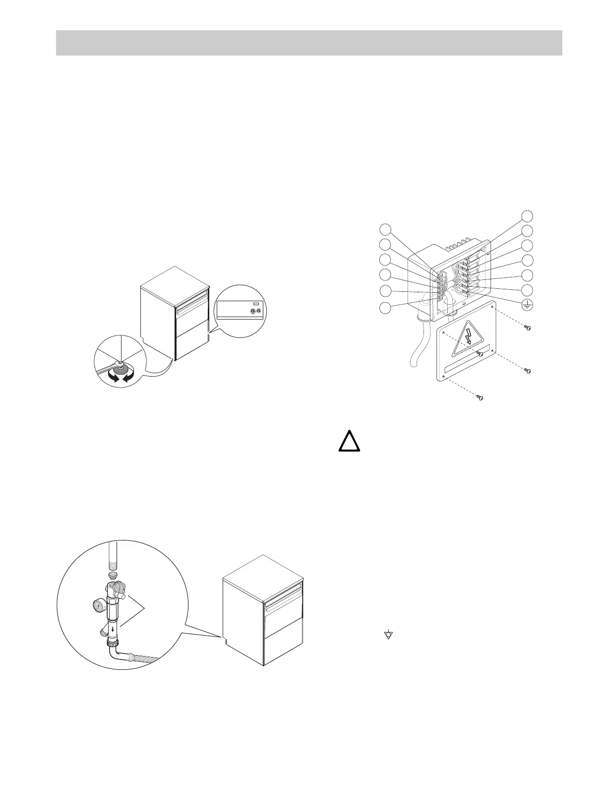
C1 RATING PLATE
The rating plate contains identification and technical
data and is located on the right-hand side panel of the
appliance (Figure 5).
Figure 5
C2 WATER CONNECTION
• Position the dishwasher and level the applia
nce by
ad
justing the appropriate bullet feet (Figure 5).
• Connect the appliance water supply pipe “A
”
(
Figure 4) (keeping with local plumbing codes) to th
e
incoming
water supply. Install a shutoff valve, Y-
Strainer, and a pressure gauge between the appli-
ance and the incoming water supply of the
unit
(F
igure 6).
Figure 6
•
Check that the dynamic water supply pressure measures
between
7.25 - 101 psi [50 - 700kPa] while dish-
washer tank or booster is filling with wa
ter.
If
the pressure is too high, install a suitable pressure
regulator on the incoming water supply to the unit.
Position the outlet pipe at a height anywhere between 29
1/2”
to 39 3/8” [750 to 1000mm] from the floor.
Check that about 0.8 gallon [3 litres] of water flow out of
the outlet pipe during the rinse cycle.
Make sure drain hose does not kink, pinch or twist,
resulting in a water flow restriction.
C3 ELECTRICAL CONNECTION
Figure 7
The installation of this unit must conform to local
codes or, in the absence of local codes, to all Natio-
nal Codes governing plumbing, sanitation, safety
and good trade practices.
• Check the over rating plate before making an
y
e
lectric supply connections. Electric supply con-
nections must agree with data on the unit rating plate.
• The earth wire at the terminal end must be
3/4”/20mm (max.) longer than the phase wires.
• The appliance requires a ground connection to
the
un
it ground screw located at the rear of the unit mar-
ked “Q” (Figure 4) in the manual and marked with the
symbol “ “ on the unit. The ground wire must ha
ve a
cr
oss section of AWG 8/8.35 mm
2
. Do not use the
wir
ing conduit or other piping for ground connectio
ns.
If ne
cessary, have the electrician supply the grou
nd
wire.
C INSTALLATION AND START-UP INSTRUCTIONS
MADE IN ITALY 2019
F.Mod.
CDT-1 Comm. Model CDT-1 Type Ref. Cadet CDT-1
PNC 9CGX50235400 Ser.Nr. 91910
MOP 40A Max 6.85 kW
MCA 34A
Nominal 6.85 kW
EL:
(208V 20A 3~ MOP 30A)
INSINGER- 6245 State Rd, Phila, PA 19135 - Warranty / Support 215-624-4800
CAUTION
THE ELECTRICAL CONNECTIONS MUST
MEET ALL NATIONAL AND ELECTRICAL
CODE REQUIREMENTS.
A
C 400....
1
11
10
9
8
7
6
5
4
3
2
12