STEP 6
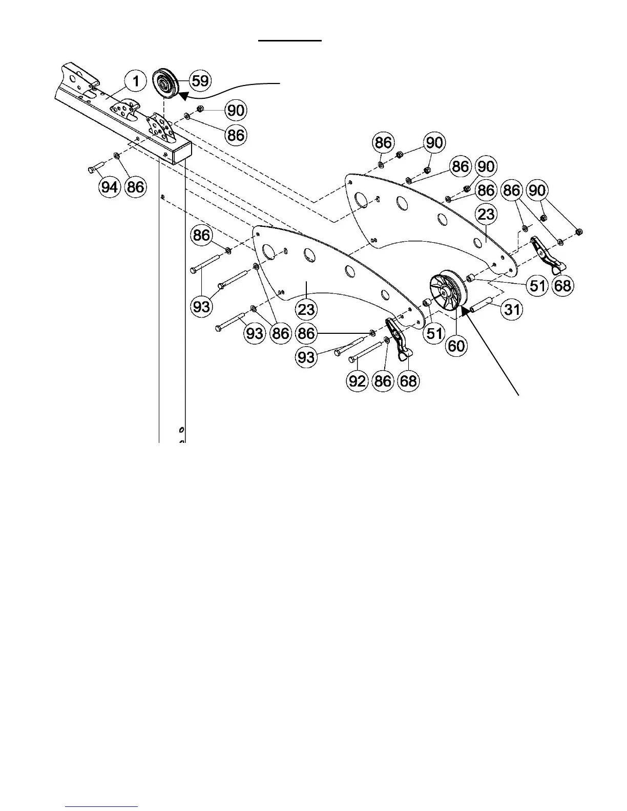
A) Install the 3.5” Pulley 1 (59) at the top of the Main Frame (1) using the M10*45 bolt (94).
Tighten this bolt now.
B) Install the Top Beam Plates (23), with the Inspire logo to the outside, to the Main Frame
using three of the M10*100 bolts (93). The lower bolt should be inserted into the upper
hole on the bottom of the Top Beam Plates. (The bottom hole is used for taller customers
who need more height to the Lat Bar.)
C) Install the 4.5” Wide Pulley 2 (60) and 5/8” Barrel Spacers (51) to the Top Beam Plates
using the last M10*100 bolt.
D) Install the Lat Bar Holders (68) with the 3” long Spacer Tube (31) to the Top Beam Plates
using the M10*115 bolt (92). The plastic nub on the end of the Lat Bar Holder will fit into
the top front hole in the Top Beam Plates. Tighten all the hardware in Steps 6 B through
D now.
PAGE 10