41
Accessory Mounting Dimensions
Product Support: www.instron.com
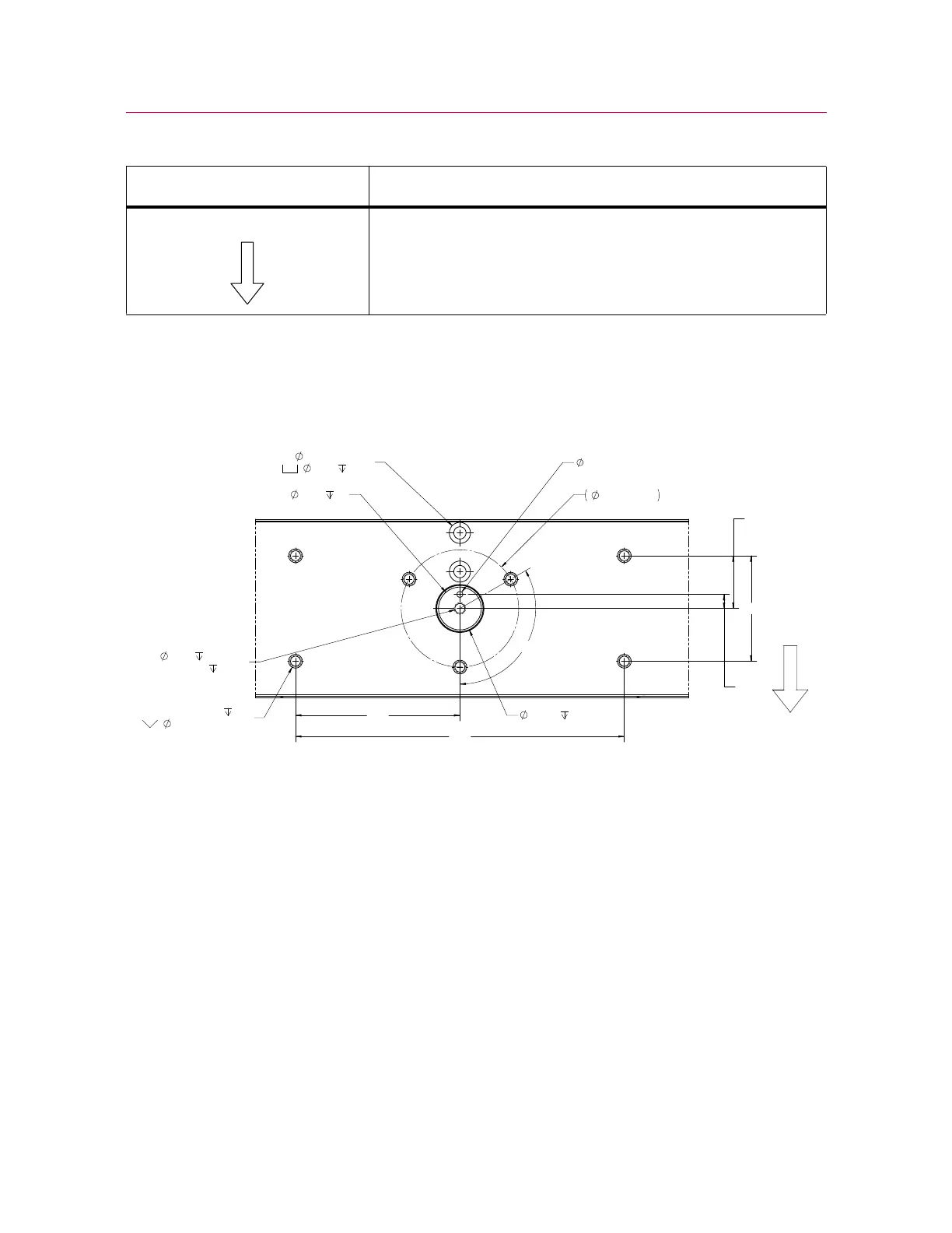
Base beam dimensions
Figure 6. View of base beam from above
arrow pointing to the front of the load frame
Table 11. Meaning of symbols on dimension drawings (Continued)
Symbol on drawing Meaning
90
45
12
140
7X M10X1.5 - 6H
25
11.75±0.25 X 90°
2X
10.5 THRU ALL
18.0 18.0
40.038
40.000
3.00 MIN
36.50
5.0
8.50 25.00
M10X1.5 - 6H 20.00
120°
100.00 PCD
5
280