Instruction Manual CVM211 Stinger
InstruTech Page 10
3.2 Electrical Installation
3.2.1 Grounding
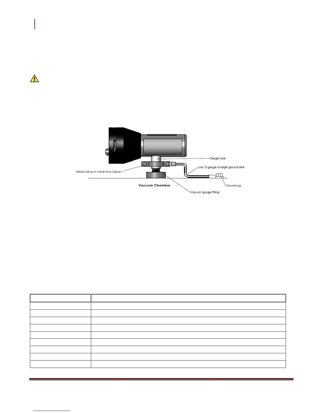
Be sure the vacuum gauge and the rest of your vacuum system are properly grounded for safety as well as
intended operation of the equipment. When using KF flanges, metal clamps must be used to ensure proper
grounding. Be aware that some vacuum fittings such as NPT connections installed using Teflon tape may not
allow for metal-to-metal contact between the vacuum gauge and the vacuum chamber. If such is the case, use
a 12 gauge or larger copper wire to connect the vacuum gauge to a ground lug on your vacuum chamber as
shown below.
3.2.2 Electrical Connections
A good recommended practice is to remove power from any cable prior to connecting or disconnecting it.
The InstruTech CVM211 will directly replace Granville-Phillips®
Mini-Convectron® modules that have a 9-pin
D-sub connector (DE-9P), and you can use your existing cables and electronics.
For new installations, fabricate a cable to connect to the signals/functions you want to use. Signals and pin
assignments are described below:
Connector and Pinout
Analog Output (Log-Linear 1-8 V, or Non-linear Granville-Phillips® compatible)
Relay Disable (Disables Relay 1 when connected to pin 4 - Ground)