DTA-7
15
13
17
14
16
19
18
NAPS-7791
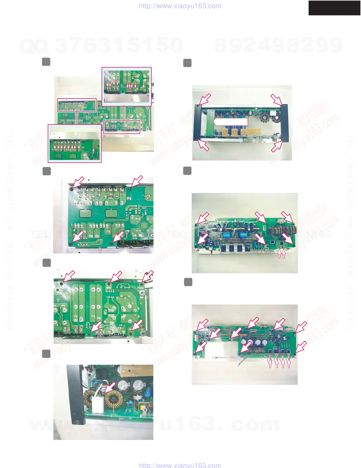
DISASSEMBLING PROCEDURES-4
DISASSEMBLING OF POWER SUPPLY UNIT
Remove 18 soldering.
Remove the four screws.
By disconnect the socket assy P801, You can remove
the PCB assy NAPS-7788.
Front side
Remove the five screws.
By doing the following work, You can separate NAPS-7789
and NAPS-7790.
1. Disconnect the terminal PCB assy NAPS-7791.
2. Remove the four screws.
By doing the following work, You can separate NAPS-7790
and the heat sink.
1. Remove two soldering.
2. Remove the six screws.
By doing the following work, You can separate NAPS-7789
and the heat sink.
1. Remove four soldering.
2. Remove the nine screws.
w
w
w
.
x
i
a
o
y
u
1
6
3
.
c
o
m
Q
Q
3
7
6
3
1
5
1
5
0
9
9
2
8
9
4
2
9
8
T
E
L
1
3
9
4
2
2
9
6
5
1
3
9
9
2
8
9
4
2
9
8
0
5
1
5
1
3
6
7
3
Q
Q
TEL 13942296513 QQ 376315150 892498299
TEL 13942296513 QQ 376315150 892498299
http://www.xiaoyu163.com
http://www.xiaoyu163.com
 Loading...