DEBUG MODE-2
DSP DEBUG MODE-2/3
TX-SR607/DTR-30.1
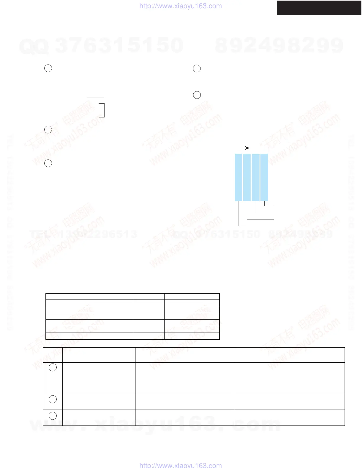
DSP Port Status
This figure is displayed in hexadecimal form.
If this is transformed to binary form, each bit indicates
the following DSP port status. Refeo to
<Fig-1>
.
7
Mute output device
This figure is displayed in hexadecimal form.
If this is transformed to binary form, each bit indicates
the IC which outputs error to microprocessor, which output
Audio Mute. Refer to
<Fig-1>
.
11
DSP Sequence
00 - FE = Not Free
2D = Mute control
FF = Free
8
bit 0: Selector IC (Q5501)
bit 1: Effector
bit 2: DSP (Q201)
bit 3: DIR (Q301)
0 = 0 0 0 0
1 = 0 0 0 1
2 = 0 0 1 0
4 = 0 1 0 0
8 = 1 0 0 0
Hexadecimal
Binary
DSP Detect Format
P = PCM (Analog)
D = Dolby Digital
d = DTS
A = AAC
S = DSD
p = Dolby Digital+
T = TrueHD
H = DTS-HD High Resolution
M = DTS-HD Master Audio
? = Unknown Format
DSP Decode
o = Decode OK
x = Decode NG
9
10
Transform
bit 0 = NIC
bit 1 = DEC
bit 2 = BUSY
bit 3 = Exec Wait
(Normal state)
(Abnormal state)
<Fig-1>
Troubleshoot by DSP DEBUG MODE
1. This debug mode will be useful in digital audio no sound or sound drop-out trouble.
2. Check information on FL display, then identify bad parts, and replace or resolder it.
3. Remdies Written below are of typical case. So, more detailed check may need in actual cases.
4. Before replace ICs below, resolder the pins first to save resources.
NOTE
Function
MPU (Main microprocessor)
DSP
DIR and DAC
Flash ROM
SDRAM
Audio processor (Selector/ Volume)
Content of Display (Continued)
No input signal to DIR.
No input signal to DIR.
No input signal to DIR.
"E" is displayed
Displayed sampling frequency
is different from input signal.
Displayed audio format is
different from input signal.
Digit No.
on FL
Symptom on FL Display
Cause of Trouble Remedy
1
4
9
1. Find out which digital input does not work.
2. Confirm where the digital waveform stops
between the digital input and DIR.
3. Resolder pins of the bad part or replace it with
new one.
The same as above.
The same as above.
Schematic Diagram
PART-5
PART-13
PART-5
PART-13
PART-13
PART-3
Circuit No.
Q701
Q201
Q301
Q282
Q281
Q5501
w
w
w
.
x
i
a
o
y
u
1
6
3
.
c
o
m
Q
Q
3
7
6
3
1
5
1
5
0
9
9
2
8
9
4
2
9
8
T
E
L
1
3
9
4
2
2
9
6
5
1
3
9
9
2
8
9
4
2
9
8
0
5
1
5
1
3
6
7
3
Q
Q
TEL 13942296513 QQ 376315150 892498299
TEL 13942296513 QQ 376315150 892498299
http://www.xiaoyu163.com
http://www.xiaoyu163.com
 Loading...