IB865 User’s Manual 13
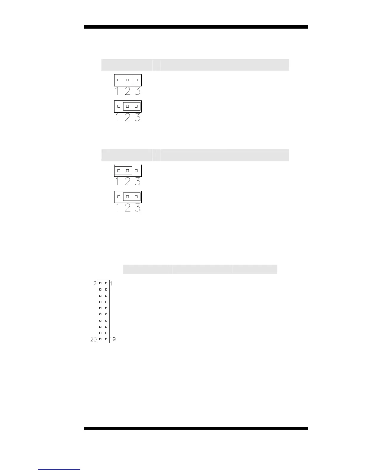
JP1: TV Type Select
JP1 Setting TV Type
Pin 1-2
Short/Closed
NTSC
Pin 2-3
Short/Closed
PAL
JP2: LVDS Panel Power Select
JP2 Setting Panel Voltage
Pin 1-2
Short/Closed
3.3V (default)
Pin 2-3
Short/Closed
5V
J2, J3: LVDS Connectors (2nd channel, 1st channel)
The LVDS connectors, DF13 20-pin mating connectors, are composed
of the first channel (J2) and second channel (J3) to support 24-bit or
48-bit.
Signal Name Pin # Pin #
Signal Name