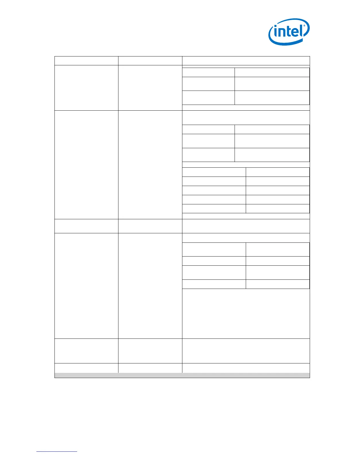
Clock Signal Name in Design Description
TMDS Bit Clock Ratio Link Speed Clock Frequency
0 TMDS clock frequency/ Symbol
per clock
1 TMDS clock frequency *4 /
Symbol per clock
TX/RX Video Clock
vid_clk
Video data clock. The video data clock frequency is derived
from the TX link speed clock based on the color depth.
TMDS Bit Clock Ratio Video Data Clock Frequency
0 TMDS clock/ Symbol per clock/
Color depth factor
1 TMDS clock *4 / Symbol per
clock/ Color depth factor
Bits per Color Color Depth Factor
8 1
10 1.25
12 1.5
16 2.0
RX TMDS Clock
tmds_clk_in
TMDS clock channel from the HDMI RX and connects to the
reference clock to the IOPLL.
RX CDR Reference Clock
iopll_outclk0
Reference clock to the RX CDR of RX transceiver.
Data Rate RX Reference Clock
Frequency
Data rate <1 Gbps 5× TMDS clock frequency
1 Gbps< Data rate
<3.4 Gbps
TMDS clock frequency
Data rate >3.4 Gbps 4× TMDS clock frequency
• Data Rate <1 Gbps: For oversampling to meet
transceiver minimum data rate requirement.
• Data Rate >3.4 Gbps: To compensate for the TMDS bit
rate to clock ratio of 1/40 to maintain the transceiver
data rate to clock ratio at 1/10.
Note:
Do not use a transceiver RX pin as a CDR reference
clock. Your design will fail to fit if you place the
HDMI RX refclk on an RX pin.
RX Transceiver Clock Out
rx_clk
Clock out recovered from the transceiver, and the frequency
varies depending on the data rate and symbols per clock.
RX transceiver clock out frequency = Transceiver data rate/
(Symbol per clock*10)
Management Clock
mgmt_clk
A free running 100 MHz clock for these components:
continued...
2 Intel FPGA HDMI Design Example Detailed Description
UG-20077 | 2017.11.06
Intel
®
FPGA HDMI Design Example User Guide for Intel
®
Arria 10 Devices
25
 Loading...


