Installing and Replacing Desktop Board Components
35
Installing and Removing System Memory
Desktop board DP55WB has four 240-pin DDR3 DIMM sockets arranged as DIMM 0 and
DIMM 1 in both Channel A and Channel B.
NOTE
The Intel P55 Express Chipset requires memory to installed in the Channel A,
DIMM 0 slot.
Guidelines for Dual Channel Memory Configuration
Before installing DIMMs, read and follow these guidelines for dual channel memory
configuration.
Two or Four DIMMs
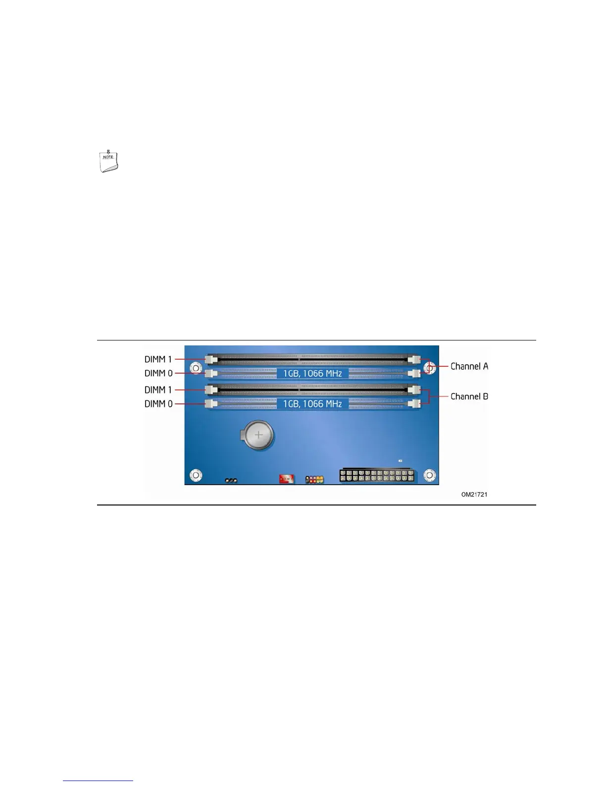
Install a matched pair of DIMMs equal in speed and size (see Figure 14) in DIMM 0
(blue) of channels A and B.
Figure 14. Example Dual Channel Memory Configuration with Two DIMMs
If additional memory is to be used, install another matched pair of DIMMs in DIMM 1
(black) in channels A and B (see Figure 15).