Intel Desktop Board DP55WB Product Guide
46
Alternate Front Panel Power LED Header
Figure 22, E shows the location of the alternate front panel power LED header. Pins 1
and 3 of this header duplicate the signals on pins 2 and 4 of the front panel header. If
your chassis has a three-pin power LED cable, connect it to this header. Table 9
shows
the p
in assignments for the alternate front panel header.
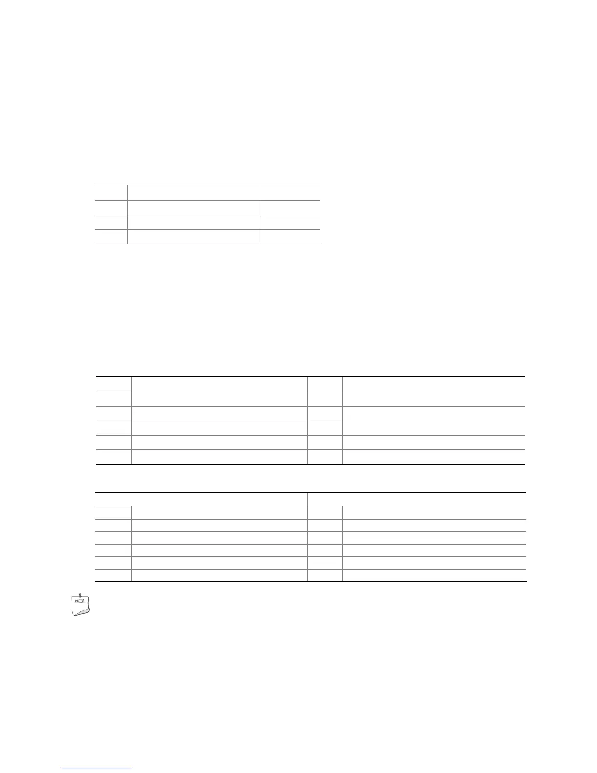
Table 9. Alternate Front Panel Power LED Header Signal Names
Pin Signal Name In/Out
1 Front panel green LED Out
2 No pin
3 Front panel yellow LED Out
USB 2.0 Headers
Figure 22, F and G show the location of the USB 2.0 headers. Table 10 shows the pin
assignments and signal names for the USB 2.0 header that supports an Intel Z-U130
USB Solid-state Drive or compatible device. Table 11 lists the pin assi
gnments
and
signal names for the standard USB 2.0 headers.
Table 10. Front Panel USB Header with Intel Z-U130 USB Solid-state Drive or
Compatible Device Support
Pin Signal Name Pin Signal Name
1 +5 VDC 2 +5 VDC
3 D- 4 D-
5 D+ 6 D+
7 Ground 8 Ground
9 KEY 10 LED#
Table 11. USB 2.0 Header Signal Names
Pin Signal Name Pin Signal Name
1 Power (+5 V) 2 Power (+5 V)
3 D- 4 D-
5 D+ 6 D+
7 Ground 8 Ground
9 Key 10 No Connection
NOTE
Computer systems that have an unshielded cable attached to a USB port might not
meet FCC Class B requirements, even if no device or a low-speed USB device is
attached to the cable. Use a shielded cable that meets the requirements for a
full-speed USB device.