Intel Desktop Board DB85FL Technical Product Specification
48
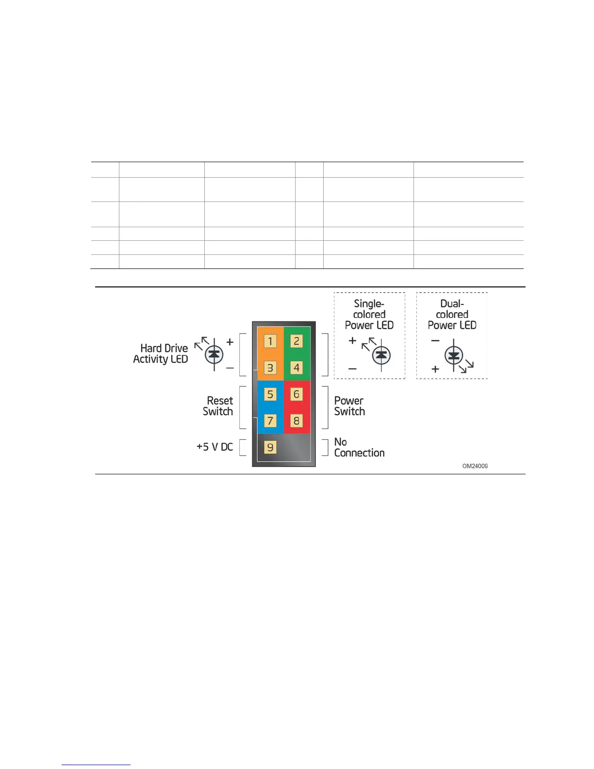
2.2.2.4 Front Panel Connector
This section describes the functions of the front panel connector. Table 24 lists the
signal names of the front panel connector. Figure 10 is a connection diagram for the
front panel connector.
Table 24. Front Panel Connector
Pin Signal Name Description Pin Signal Name Description
1 HDD_POWER_LED Pull-up resistor
(750 Ω) to +5 V
2 POWER_LED_MAIN [Out] Front panel LED
(main color)
3 HDD_LED# [Out] Hard disk
activity LED
4 POWER_LED_ALT [Out] Front panel LED
(alt color)
5 GROUND Ground 6 POWER_SWITCH# [In] Power switch
7 RESET_SWITCH# [In] Reset switch 8 GROUND Ground
9 +5 V_DC Power 10 Key No pin
Figure 10. Connection Diagram for Front Panel Connector
2.2.2.4.1 Hard Drive Activity LED
Pins 1 and 3 can be connected to an LED to provide a visual indicator that data is
being read from or written to a hard drive. Proper LED function requires a SATA hard
drive or optical drive connected to an onboard SATA connector.
2.2.2.4.2 Reset Switch
Pins 5 and 7 can be connected to a momentary single pole, single throw (SPST) type
switch that is normally open. When the switch is closed, the board resets and runs the
POST.