Installing and Replacing Desktop Board Components
47
Front Panel Header
See Figure 22, C for the location of the front panel header. Table 8 shows the pin
assignments for the front panel header.
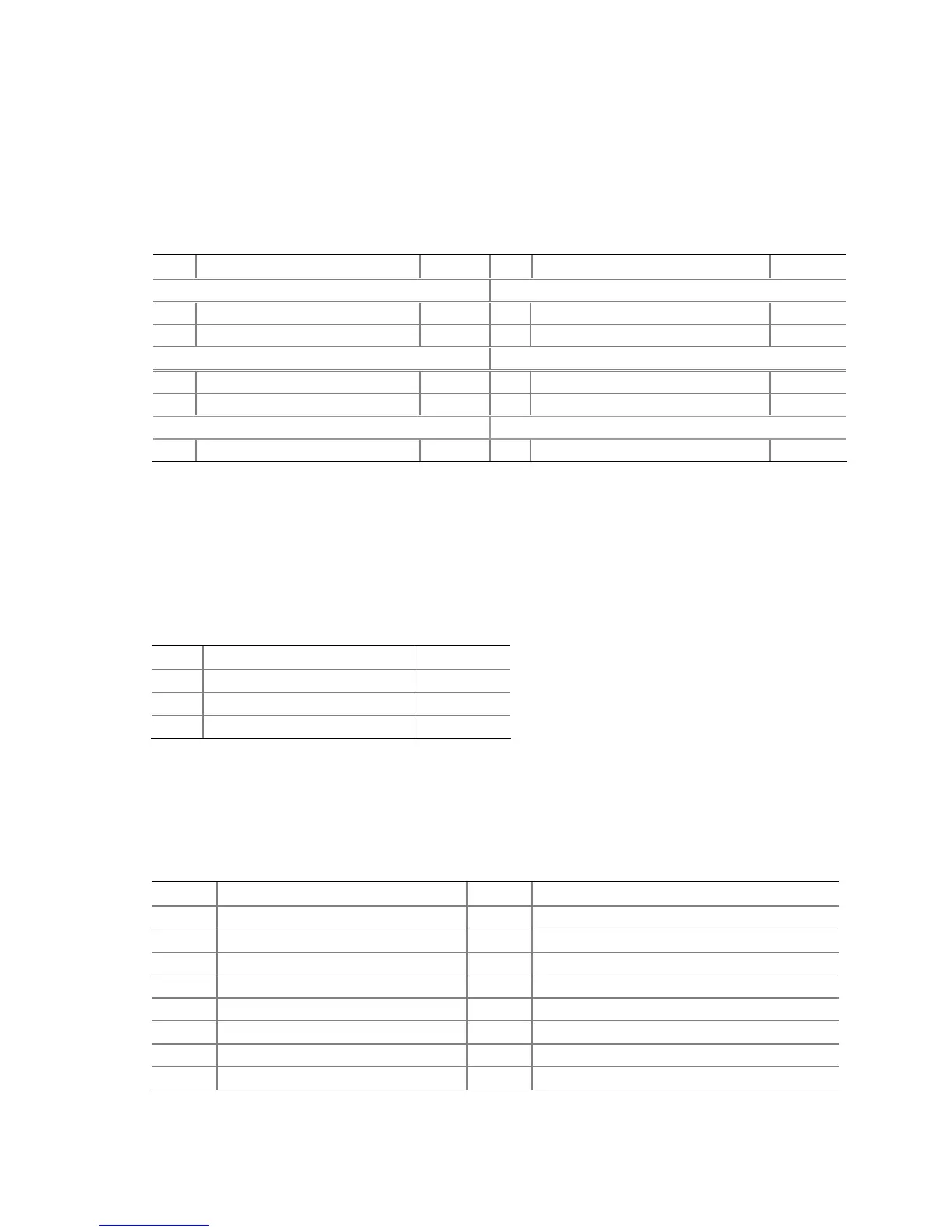
Table 8. Front Panel Header Signal Names
Pin Signal Name In/Out
Pin Signal Name In/Out
Hard Drive Activity LED Power LED
1 Hard disk LED pull-up to +5 V
Out 2 Front panel green LED Out
3 Hard disk active LED Out 4 Front panel yellow LED Out
Reset Switch On/Off Switch
5 Ground 6 Power switch In
7 Reset switch In 8 Ground
Power Not Connected
9 Power Out 10 No pin
Alternate Front Panel Power LED Header
Figure 22, D shows the location of the alternate front panel power LED header. Pins 1
and 3 of this header duplicate the signals on pins 2 and 4 of the front panel header. If
your chassis has a three-pin power LED cable, connect it to this header. Table 9
shows
the p
in assignments for the alternate front panel header.
Table 9. Alternate Front Panel Power LED Header Signal Names
Pin Signal Name In/Out
1 Front panel green LED Out
2 No pin
3 Front panel yellow LED Out
HD Audio Link Header
See Figure 22, E for the location of the HD Audio Link header. Table 10 shows the pin
assignments for the header.
Table 10. HD Audio Link Header Signal Names
Pin Signal Name Pin Signal Name
1 BCLK 2 Ground
3 RST# 4 3.3 Vcc
5 SYNC 6 Ground
7 SDO 8 3.3 Vcc
9 SDI0 10 +12 V
11 SDI1 12 Key
13 No Connection 14 3.3 V STBY
15 No Connection 16 Ground