Installing and Replacing Desktop Board Components
49
Chassis Intrusion Header
Figure 22, G shows the location of the chassis intrusion header. This header can be
connected to a mechanical switch on the chassis to detect if the chassis cover is
removed. Table 12 shows the pin assignments for t
h
e chassis intrusion header.
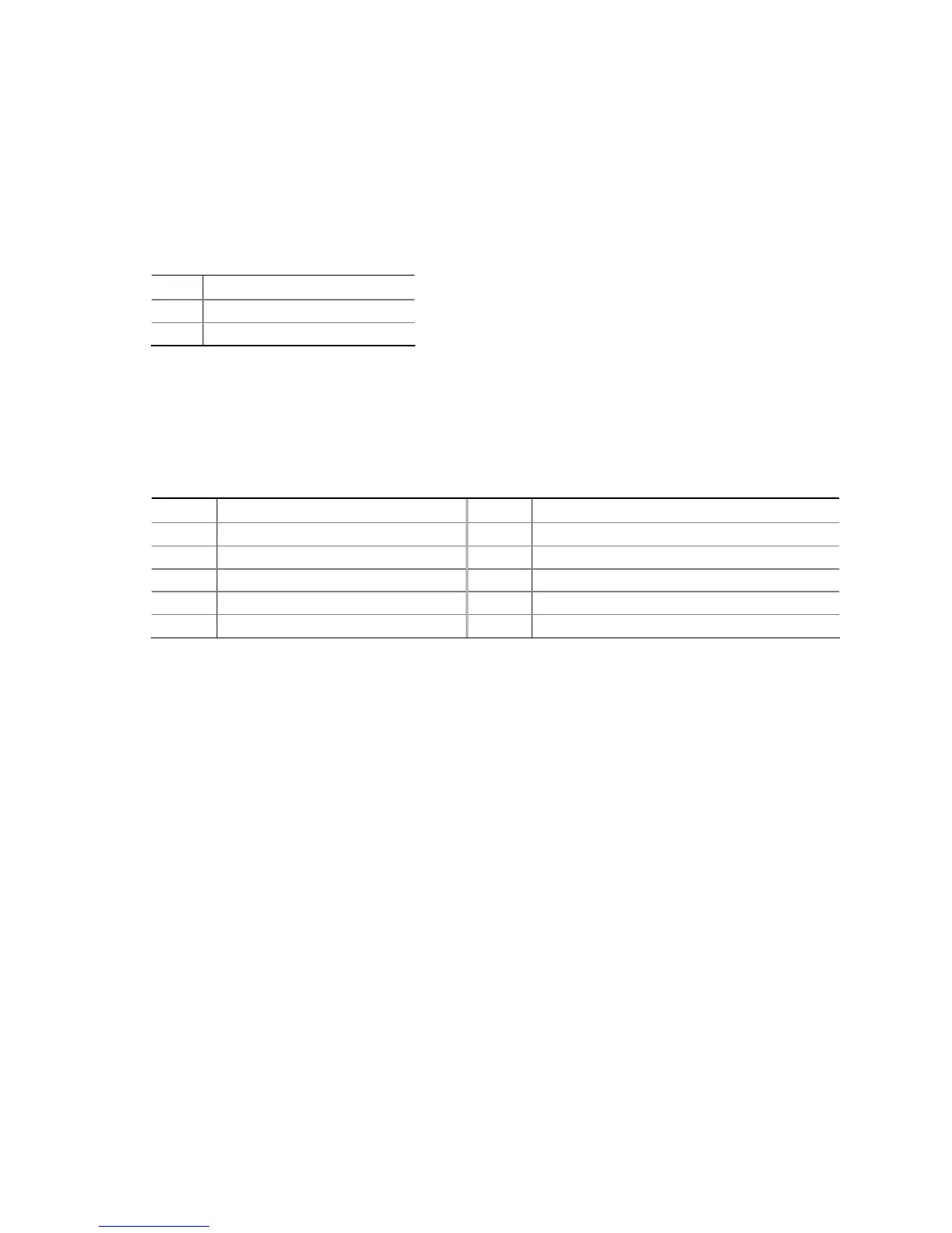
Table 12. Chassis Intrusion Header Signal Names
Pin Signal Name
1 Ground
2 Intruder#
Serial Port Header
See Figure 22, H for the location of the serial port header. Table 13 shows the pin
assignments for the header.
Table 13. Serial Port Header Signal Names
Pin Signal Name Pin Signal Name
1 DCD 2 RXD#
3 TXD# 4 DTR
5 Ground 6 DSR
7 RTS 8 CTS
9 RI 10 No Connection