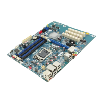
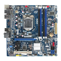
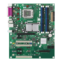
Intel Desktop Board DP67BG Product Guide
26
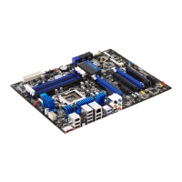
Diagnostic LEDs
The Desktop Board provides eight LEDs that allow you to monitor the board’s progress
through the BIOS Power-on Self-Test (see Figure 6). At initial power on, all the LEDs
are off. W
hen the BIOS starts an activity such as memory initialization, the
corresponding LED starts flashing. Once the activity has completed, the LED will
remain on.
Table 5. Diagnostic LEDs
Item/Callout
in Figure 6
Activity
LE
D
Color
Description
A Watch Dog Timer Fire/
Back to BIOS
Red When the watch dog timer fires to reset
the board, this LED will flash.
In addition, this LED will light and stay
on when the Back to BIOS button has
been pressed.
B Processor Initialization Green This LED will flash when the processor
initialization activity starts. Then the
LED will stay on when processor
initialization is complete.
C Memory Initialization Green This LED will flash when the memory
initialization activity starts. Then the
LED will stay on when memory
initialization is complete.
D Video Initialization Green This LED will flash when the video
initialization activity starts. Then the
LED will stay on when video
initialization is complete.
E USB Initialization Green This LED will flash when the USB
initialization activity starts. Then the
LED will stay on when USB initialization
is complete.
F Hard Drive Initialization Green This LED will flash when the hard drive
activity starts. Then the LED will stay
on when hard drive initialization is
complete.
G Option ROM Initialization Green This LED will flash when the option ROM
activity starts. Then the LED will stay
on when option ROM initialization is
complete.
H OS Start Green Just before BIOS transfers control to
the operating system, this LED will light
and stay on.