Installing and Replacing Desktop Board Components
53
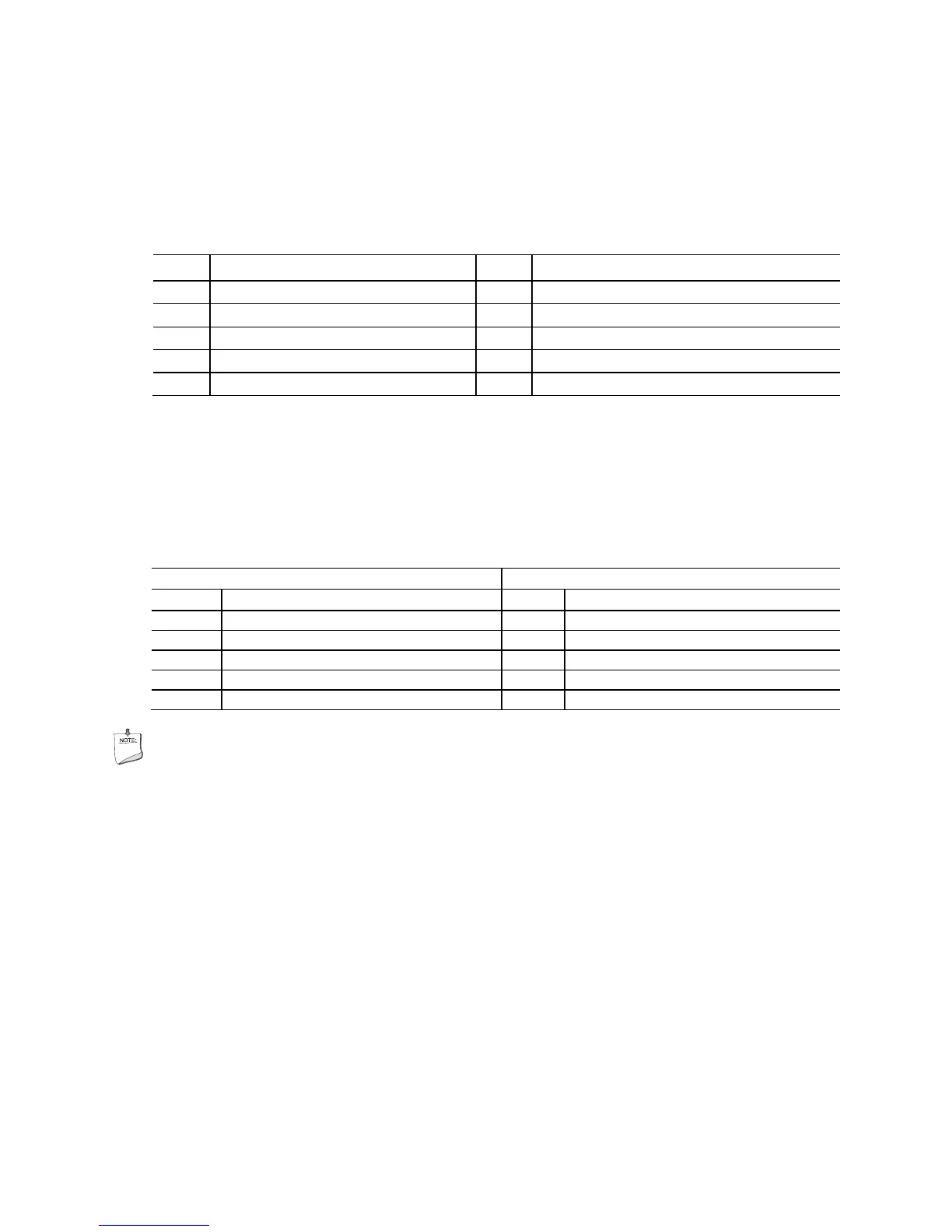
Serial Header
Figure 24, I shows the location of the serial headers. Table 14 shows the pin
assignments and signal names for each serial header.
Table 14. Serial Port Header
Pin Signal Name Pin Signal Name
1 DCD (Data Carrier Detect) 2 RXD# (Receive Data)
3 TXD# (Transmit Data) 4 DTR (Data Terminal Ready)
5 Ground 6 DSR (Data Set Ready)
7 RTS (Request To Send) 8 CTS (Clear To Send)
9 RI (Ring Indicator) 10 Key (no pin)
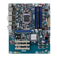
USB 2.0 Headers
Figure 24, J shows the location of the four USB 2.0 headers. Table 15 shows the pin
assignments and signal names for each USB 2.0 header. Each USB 2.0 header can be
used to connect two USB devices.
Table 15. USB 2.0 Header Signal Names
Port A Port B
Pin Signal Name Pin Signal Name
1 Power (+5 V) 2 Power (+5 V)
3 D- 4 D-
5 D+ 6 D+
7 Ground 8 Ground
9 Key 10 No Connection
NOTE
Computer systems that have an unshielded cable attached to a USB port might not
meet FCC Class B requirements, even if no device or a low-speed USB device is
attached to the cable. Use a shielded cable that meets the requirements for a
full-speed USB device.