Intel
®
E7500 and Intel
®
E7501 Chipsets MCH Thermal Design Guide
18 Thermal Design Guide
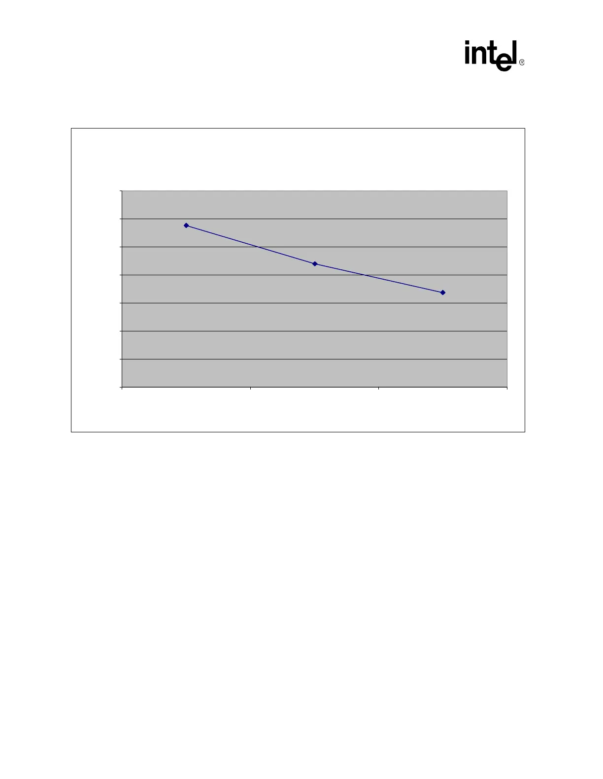
Figure 7 shows the theta ja versus airflow for the reference thermal solution.
6.2 Mechanical Design Envelope
Though each design may have unique mechanical volume and height restrictions or
implementation requirements, the height, width, and depth constraints typically placed on the Intel
E7500 chipset and Intel E7501 chipset MCHs in embedded environments are shown in Figure 8.
These constraints assume the use of the CompactPCI
*
blade form factor.
When using heat sinks that extend beyond the MCH reference heat sink envelope shown in
Figure 8, any motherboard components placed between the underside of the heat sink and
motherboard cannot exceed 2.286 mm [0.090 in] in height.
Figure 7. Theta ja versus Airflow for the Reference Thermal Solution
E7500 and E7501 MCH Reference Thermal Solution
Theta ja vs. Airflow
5.8
4.4
3.4
0.00
1.00
2.00
3.00
4.00
5.00
6.00
7.00
50 100 200
Airflow (LFM)
Theta ja (C/W)