Intel
®
E7500 and Intel
®
E7501 Chipsets MCH Thermal Design Guide
24 Thermal Design Guide
6.3.2.3 Heat Sink Push-Pin
Four push-pins are required to implement Retention Method B. Vendor information and a detailed
mechanical drawing are located in Appendix B. Currently, the push-pin is available for 0.096 inch
thick motherboards. Other size motherboards might require custom parts from the vendor.
6.3.3 Mechanical Interface Material
Intel recommends the use of a mechanical interface material to avoid cracking of the exposed die
under loading. The interface material reduces mechanical loads experienced by the die. The
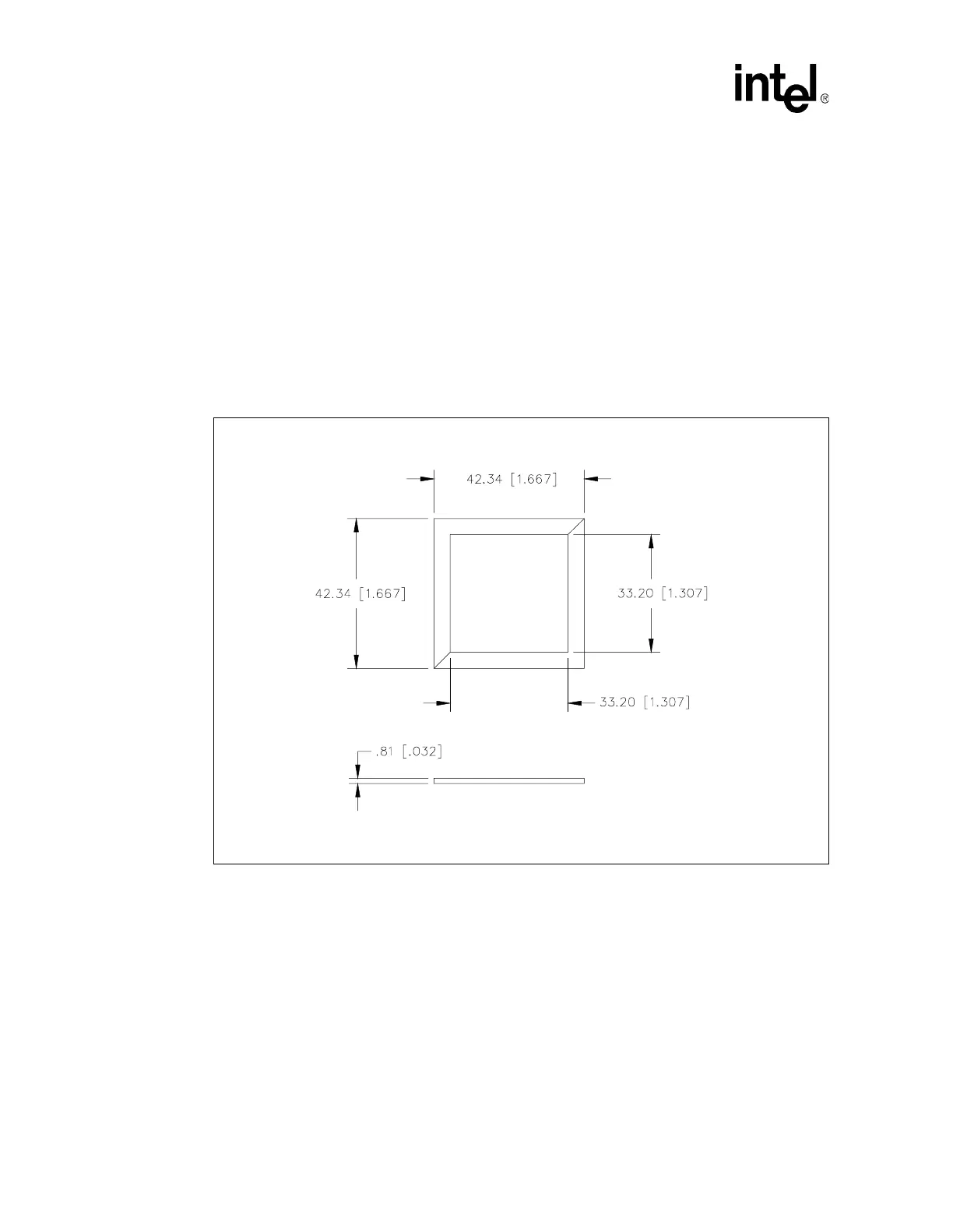
reference thermal solution uses a picture frame gasket of 0.813 mm [0.032 in] thick Poron* foam.
The foam gasket is a two-piece design, with diagonal cuts at two corners, as shown in Figure 14.
A one-piece gasket design may be used instead without any impact to mechanical performance.
6.3.4 Thermal Interface Material
A thermal interface material provides improved conductivity between the die and heat sink. The
reference thermal solution is delivered with Powerstrate 51* (manufactured by Power Devices,
Inc.) phase change material attached.
Figure 14. Heat Sink Mechanical Gasket, Optional Two-Piece
NOTE: Drawing dimensions are in millimeters [in] and are not to scale.