D
IGITAL PA SYSTEM
11
PSI-5120A/5240A
13. FM ANTENNA TERMINAL
C
onnect the FM antenna. Please locate the antenna to the position where stations are tuned well.
14. MIC INPUT 2~5
These inputs are suitable to receive signal from microphones. XLR inputs are balanced input.
Input Level : -60dBV ~ -16dBV
When other line level source is connected to one of these terminals, adjust the trim volume to -16dB position.
The phantom switch must be off, or not the line level source may be damaged.
Method to Connect Speakers
Method to Connect Speakers
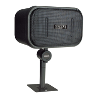
- Installation of speaker
Before connecting speakers, disconnect the AC power cable. Note the proper connecting terminals as shown
below. Make certain that the total impedance is not less than the rated impedance indicated.
- Rated output and impedance
※Caution : Be sure that total impedance is not less than the rated impedance. (See upper chart.)
Do not connect the low impedance speaker to the high impedance terminals.
※WARNING : Extreme care must be exercised when connecting high-impedance systems, as potentially
hazardous voltages may be present at these terminals.
Do not install this equipment in a confined space with less than adequate ventilation.
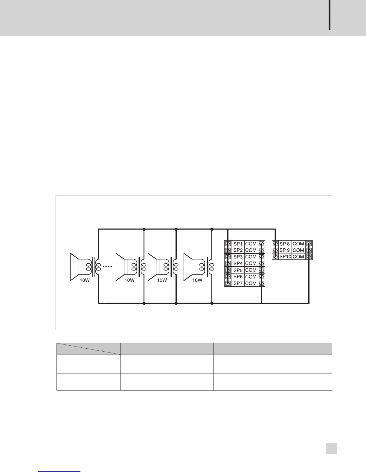
HIGH IMPEDANCE SPEAKER INSTALLATION
※Total power sum of all zones (1~10) must not exceed the rated power.
PSI-5120A:120W, PSI-5240A:240W
※Do not use 4Ω speaker terminal and high impedance speaker terminals at the same time.
4Ω (LOW IMPEDANCE) SP 1~10 (HIGH IMPEDANCE)
PSI-5120A 22V/4Ω
(120W)
EC & Associated : 100V/83Ω
USA/CANADA &
Associated : 70V/41Ω
PSI-5240A 31V/4
Ω
(240W)
EC & Associated : 100V/42Ω
USA/CANADA &
Associated : 70V/21Ω
MODEL
OUTPUT