Air Fx Irrigator Instructions for Use – US Page 7
2.4 Connection Panel Dictionary
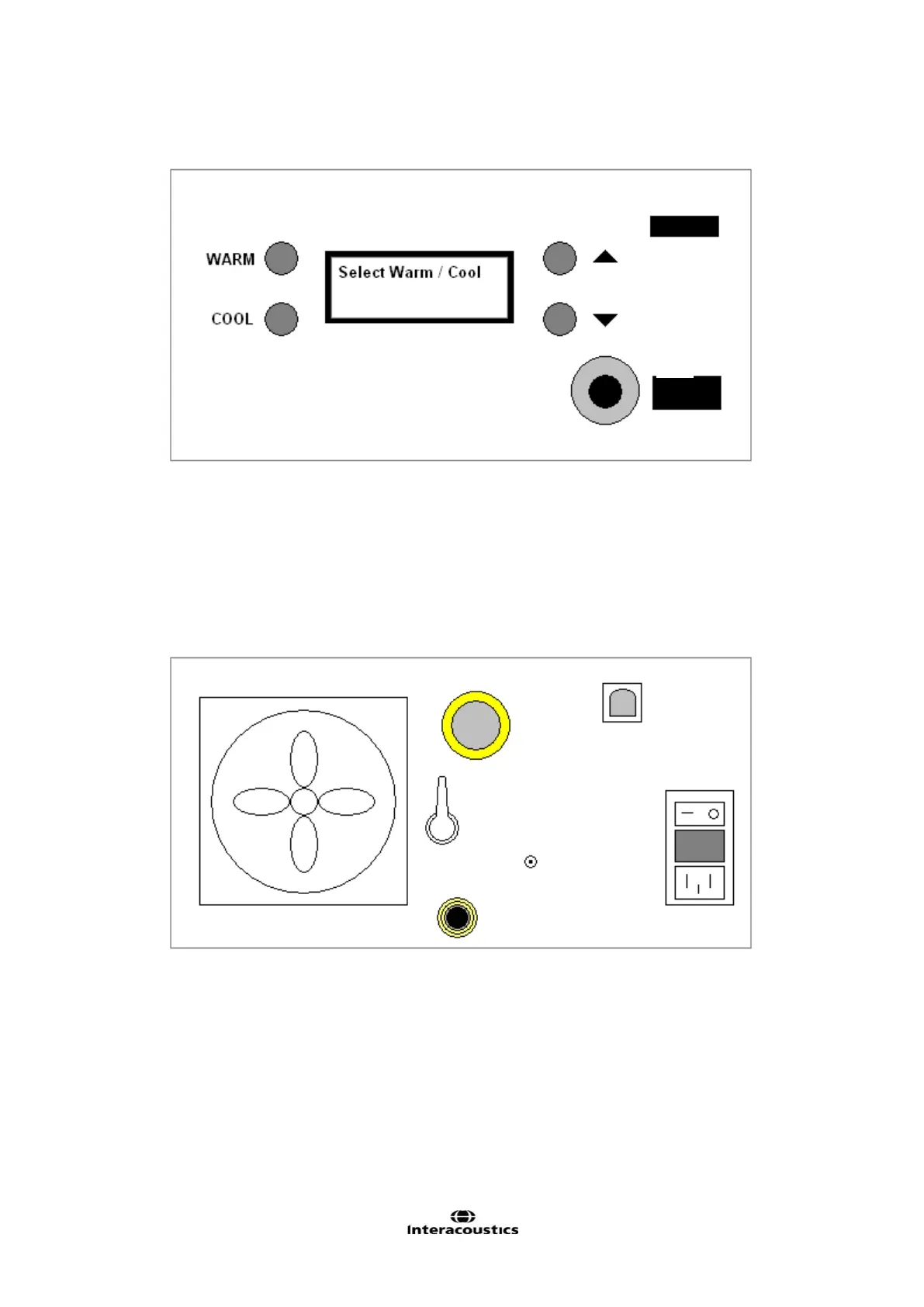
Figure 1 Front Panel Diagram
A Specifies Warm Irrigation to be performed / returns to standby state
B Specifies Cool Irrigation to be performed / returns to standby state
C Adjust temperature set point up 1°C
D Adjust temperature set point down 1°C
E Hose connection
F Handle support
G LCD output screen
Figure 2 Rear Panel Diagram
A Exhaust fan F Fuse
B Air Inlet Filter G Ground Screw
C USB B Connector H AC Input
D Power Switch I Fill / Drain Water Outlet
E Fill / Drain Valve