Do you have a question about the Interacoustics Eclipse and is the answer not in the manual?
Provides information about the manual's scope, validity, and product manufacturer.
Details the intended use of the Eclipse system and its modules for ear disorder diagnosis.
Specifies the qualifications required for operating the Eclipse system, such as audiologists.
Defines the target age groups for the Eclipse system modules, noting exceptions.
Lists conditions under which the Eclipse system should not be used, e.g., ear infections.
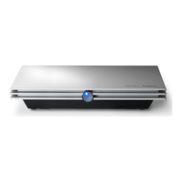
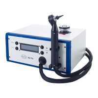
Describes the Eclipse device, its modules, and included system components.
Explains the meaning of Warning, Caution, and Notice labels used throughout the manual.
Instructions for unpacking, inspecting for damage, reporting faults, and storage.
Explains the various symbols and markings found on the instrument, e.g., CE-mark, SN.
Details the process of connecting the Eclipse to mains power and computer for safe operation.
Explains how to use the ground plug to reduce noise during evoked potential testing.
Identifies and describes the ports on the back panel of the Eclipse device.
Identifies and describes the power indication indicator on the front panel.
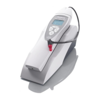
Explains the functions of the preamplifier dial, button, and LED indicators for impedance.
Provides step-by-step instructions for installing the Eclipse module software.
Lists prerequisites and important notices before starting software installation.
Specifies minimum hardware and operating system requirements for the PC.
Lists the necessary items for installing the Eclipse software.
Step-by-step guide to installing the Eclipse module software via USB.
Instructions for installing the necessary drivers for the Eclipse hardware to function.
How to restore default factory protocols in the software.
Guide to installing language packs for the Eclipse software interface.
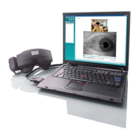
Explains the functionality of the software in reader station mode for viewing recordings.
Information on licensing Eclipse software modules and tests for system functionality.
Location of the Eclipse hardware serial number on the instrument.
How to access DSP serial number and license key via software.
Steps to start the Eclipse module from OtoAccess® Database for patient management.
Refers to the database instruction manual for module setup.
Steps to start Eclipse modules from Noah patient management software.
Describes elements of the Record Tab for data acquisition and waveform viewing.
Explains File, Edit, and View menu options for managing recordings and display.
How to access electronic help features and context-sensitive information within the software.
Navigating through previously saved test sessions using PgUp/PgDn keys.
How to select a test protocol from a dropdown menu for a new test.
Allows temporary changes to protocol settings for the current session only.
Displays curves with equal distance between them for better visual comparison.
Groups waveforms with identical parameters for easier review.
Accesses the report editor for selecting or creating report templates.
Prints the report for the selected session using printer layout setup.
Shows A and B curves for selected waveform, typically for alternating polarity.
Displays the contralateral waveform for the selected waveform.
Activates talk forward function, pausing the test temporarily.
Displays only the selected curve for easier visual evaluation.
Displays Right and Left waveforms on separate sides of the screen.
Saves the current session and starts a new one without closing software.
Saves the current test session and closes the software.
Selects different stimulus rates from a dropdown menu.
Selects different stimulus frequencies from a dropdown menu.
Displays current stimulus parameters like level, type, and filter settings.
Allows manual selection of stimulus intensity and test ear.
Shows the number of accepted and rejected sweeps during testing.
Indicates correlation between two curves for waveform reproducibility assessment.
Buttons to start and stop the measurement process.
Allows pausing during a test, stimulus continues but no measurement occurs.
Moves to the next intensity selected in Manual Stimulus window.
Provides information on curve quality via Fmp and residual noise graphs.
Increases the number of sweeps/averages during testing for better results.
Displays ongoing raw EEG, indicating rejection status with color coding.
Opens advanced EEG graph for detailed adjustments and analysis.
Option to hide stimulus artifacts for easier waveform evaluation.
Adjusts the display gain for waveform curves using arrow keys or Ctrl+arrows.
Edits the recording window duration using arrow keys on the graph.
How to select individual waveforms for editing or viewing using Tab keys.
Drags a waveform curve up or down by its handle to adjust its position.
Shows differential waveforms like A-B or Ipsi-Contra for analysis.
Adds a short comment to a waveform for later reference.
Monitors the rejection status via an oval light indicator on screen.
Marks specific points on waveforms for analysis using buttons or keyboard.
Removes waveform markers from selected curves via right-click menu.
Automatically places markers based on normative latency data.
Displays normative latency data on screen for selected curves.
Permanently deletes individual waveform curves from the session.
Adjusts the display gain (zoom) for individual waveform curves.
Temporarily hides individual waveform curves from view.
Fixates curves for comparison with historic sessions.
Combines two selected curves into a single sum curve.
Adds curves together to generate a third curve from their average.
Displays the difference between ipsilateral and contralateral waveforms.
Displays the difference between waveform A and waveform B.
Modifies display filters to remove unwanted noise from recordings.
Displays recording parameters for each curve.
Adds comments to individual curves for later reference.
Enables and uses a double cursor for precise measurement on waveforms.
Calculates SNR by placing wave V marker and SN10 marker.
Categorizes waveforms using specific markers (CR, RA, INC).
Describes elements for analyzing waveform latencies and interpeak values.
Displays latencies of marked waveforms for left and right ears.
Displays interpeak latency values and interaural differences.
Graphical presentation of waveform latencies relative to stimulus intensity.
Disables desktop composition in Windows 7 for smoother cursor movement.
Enables trough markers for peak-to-trough amplitude calculation.
Troubleshooting steps for Help function issues in Windows 7, 8, & 10.
Lists keyboard shortcuts for various software functions for efficient operation.
Instructions for preparing the patient before starting tests, including skin prep.
Steps for checking electrode impedance before testing to ensure quality.
Guidance on correctly placing transducers on the patient for accurate results.
Guidance on performing ABR threshold recordings for hearing loss assessment.
Typical electrode placement for ABR threshold recording.
Lists available stimuli for ABR threshold testing.
How to edit ABR threshold recordings, typically for NB CE-chirp or Tone Burst.
Guidance on interpreting ABR results and using correction factors.
Guidance for neuro testing to determine auditory pathway function.
Typical electrode placement for neuro latency recording.
How to edit neuro latency recordings and analyze response changes.
Graphical presentation of waveform latencies relative to stimulus intensity.
Guidance for eABR testing to determine cochlear tuning.
Provides two electrode placement options for eABR testing.
How to edit eABR recordings, including handling CI artifacts.
Tool for estimating current levels for cochlear implant tuning.
Guidance for ECochG recording to assess cochlear responses.
Describes electrode montages for ECochG (TipTrode, TMtrode).
Shows examples of marked points for ECochG amplitude and area ratio.
Guidance for CM recording to diagnose auditory neuropathy spectrum disorder.
Electrode placement for CM recording.
Specifies stimuli for CM measurements.
Shows an example of a CM recording for ANSD diagnosis.
Explains how to interpret CM results for ANSD patients.
Guidance for AMLR recording to assess auditory pathway integrity.
Electrode placement for Auditory Middle Latency Response testing.
Lists available stimuli for AMLR testing.
Shows an example AMLR recording for threshold evaluation.
Guidance for ALR/ACR recording to assess hearing loss in adults.
Electrode placement for ALR threshold recording.
Lists available stimuli for ALR threshold testing.
Explains interpretation of ALR results and correction factors.
Uses ALR threshold correction factors for infant hearing aid fitting.
Guidance for P300/MMN recording to evaluate auditory function.
Electrode placement for P300/MMN recording.
Lists available stimuli for P300/MMN testing.
Summarizes parameters for P300 and MMN recordings.
Describes LBK15 box for checking system performance and quality.
Automatic preamplifier gain setting for VEMP tests to handle muscle potentials.
Displays ongoing EMG contraction/activity during VEMP testing.
Explains P1, N1, P1', N1' markers for VEMP waveforms and latency data.
Calculates asymmetry ratio between VEMP curves by linking them.
Scales raw VEMP amplitudes to compensate for muscle contraction variations.
Guidance for cVEMP testing to assess vestibular function.
Electrode placement for cervical Vestibular Evoked Myogenic Potential testing.
Lists available stimuli for cVEMP testing.
Specifies default settings for cVEMP stimulus and recording.
Step-by-step guide for performing cVEMP tests, including patient instructions.
How to mark peaks and set VEMP partners in cVEMP results.
Shows an example of a cVEMP recording with a lowered threshold.
Guidance for oVEMP testing to assess vestibular function.
Electrode placement for ocular Vestibular Evoked Myogenic Potential testing.
Lists available stimuli for oVEMP testing.
Specifies default settings for oVEMP stimulus and recording.
Step-by-step guide for performing oVEMP tests, including patient instructions.
How to mark peaks and set VEMP partners in oVEMP results.
Logs each sweep for later replay and analysis in Matlab/Excel.
Exports averaged curves or full sessions for further analysis.
Exports the full session of averaged data seen on screen.
Exports recorded data when the Eclipse is not connected.
Adds and calibrates WAV files for stimuli for use in tests.
Proper handling and selection of Sanibel™ OAE ear tips for accurate measurements.
Recommends daily checks for OAE equipment to ensure functionality.
Tests probe integrity to detect artifacts or system distortions.
Performs a real-ear check to verify expected OAE results.
Advises on PC power settings to prevent IA OAE Suite crashes.
Lists compatible devices with the IA OAE Suite software.
Instructions for starting IA OAE Suite from OtoAccess® Database.
Instructions for starting IA OAE Suite from Noah 4.
Enables simulation mode for practicing protocols without actual testing.
Describes how to log and send crash reports for the IA OAE Suite.
Describes menu access for Setup, Print, Edit, and Help in DPOAE/TEOAE modules.
Guidance on using the Distortion Product Otoacoustic Emissions module.
Patient instructions, ear canal inspection, and equipment preparation for DPOAE.
Explains Menu, Guidance, Print, Save options in DPOAE module.
Guidance on using the Transient Evoked Otoacoustic Emissions module.
Patient instructions, ear canal inspection, and equipment preparation for TEOAE.
Explains Menu, Guidance, Print, Save options in TEOAE module.
General precautions and instructions for using the ASSR module.
Importance of patient preparation for reliable ASSR test results.
Detailed steps for preparing the patient skin and placing electrodes.
How to prepare the skin for electrode placement to ensure low impedance.
Instructions for placing electrodes on the patient's head.
Crucial step to check electrode impedance for acceptable results.
Ensures electrode cables are properly plugged in and connected.
Visual guide to checking electrode impedance using the preamplifier.
LBK15 unit usage for functional testing of ASSR.
Overview of the ASSR Tab for starting, monitoring, and controlling tests.
Explains File menu options for System setup, printing, and exiting.
How to select a test protocol from a dropdown menu.
Allows temporary protocol changes for the current session.
Opens the report editor for creating or selecting report templates.
Prints the selected session's report using the print wizard setup.
Saves the current session and closes the ASSR software.
Accesses and reviews past ASSR test sessions.
Displays frequencies and stimulus intensities for ASSR testing.
Shows elapsed test time and transducer used for the ASSR session.
Selects the appropriate stimulus rate (40Hz or 90Hz) for ASSR testing.
Guidance on performing Auditory Steady-State Response recordings.
Buttons to start and stop the ASSR measurement process.
Allows pausing during an ASSR test, with option to resume.
Displays ongoing raw EEG for ASSR, indicating rejection status.
Shows ongoing or completed ASSR results for specified stimuli.
Displays ASSR detection information, probability, and residual noise.
Allows extending test time for all frequencies or specific frequencies.
Adjusts stimulus intensity for the entire ear or specific frequencies.
Stops the current ongoing intensity in the ASSR test.
Utility for deciding and calculating masking noise levels in ASSR.
Displays estimated audiogram and allows modification of correction factors.
Explains symbols used in ASSR audiograms, matching audiometry standards.
How audiometric symbols are saved and displayed in Noah or OtoAccess.
Explains how the estimated audiogram is generated based on detected ASSRs.
Shows how AC and BC results are displayed together in the audiogram.
Symbol displayed when no response is detected in the audiogram.
Dropdown to select appropriate correction factors for recordings.
Lists keyboard shortcuts for the audiogram tab.
Recommendations for care and maintenance to ensure performance and safety.
Instructions for cleaning instruments and accessories safely.
Importance and procedure for keeping OAE probe tips clean for accurate measurements.
Conditions for Interacoustics responsibility regarding repairs and modifications.
Details the warranty terms for the Eclipse device and accessories.
Lists hardware specifications including CE-mark, standards, power, and dimensions.
Details technical specs for EP15, EP25, and VEMP modules.
Provides correction values for converting peSPL to nHL for various stimuli.
Lists technical specifications for the TEOAE module.
Lists technical specifications for the DPOAE module.
Lists technical specifications for the ASSR module.
Information on EMC compliance and precautions for instrument use.
Overview of functionalities for EP15/EP25/VEMP modules.
Compares test types and functionalities across EP15, EP25, and VEMP modules.
Details maximum stimulus intensity for various transducers.
Lists test types and functionalities for the TEOAE module.
Lists test types and functionalities for the DPOAE module.
Lists functionalities for the ASSR module.
| Category | Medical Equipment |
|---|---|
| Manufacturer | Interacoustics |
| OAE | Yes |
| ABR | Yes |
| Stimulus | Clicks, Tone Bursts, Chirps |
| Transducer | Insert earphones, Headphones |
| Connectivity | USB |
| Applications | Newborn hearing screening |
| Software | Eclipse Software Suite |
| Battery Life | Not applicable (mains powered) |