Intergas Heating Ltd 34
10.2 Setting via the service code
The boiler controller in the appliance is factory set in accordance with the parameters.
These parameters can only be changed using the service code. Proceed as follows to activate
the program memory:
1. Press the and keys simultaneously until a 0 appears on the service- and
temperature display.
2. Using the and keys set 15
(service code) on the temperature display.
3. Using the key select the parameter to be set on the service display.
4. Using the and keys set the parameter to the desired value (visible) on the
temperature display.
5. Once all desired changes have been entered, press the key until a P appears on the
service display.
The boiler controller has now been reprogrammed.
•
Pressing the key in takes you out of the menu without storing the parameter changes.
•
By pressing the button over 5 seconds the default setting for the parameters will be restored. In the display “F-set” appears.
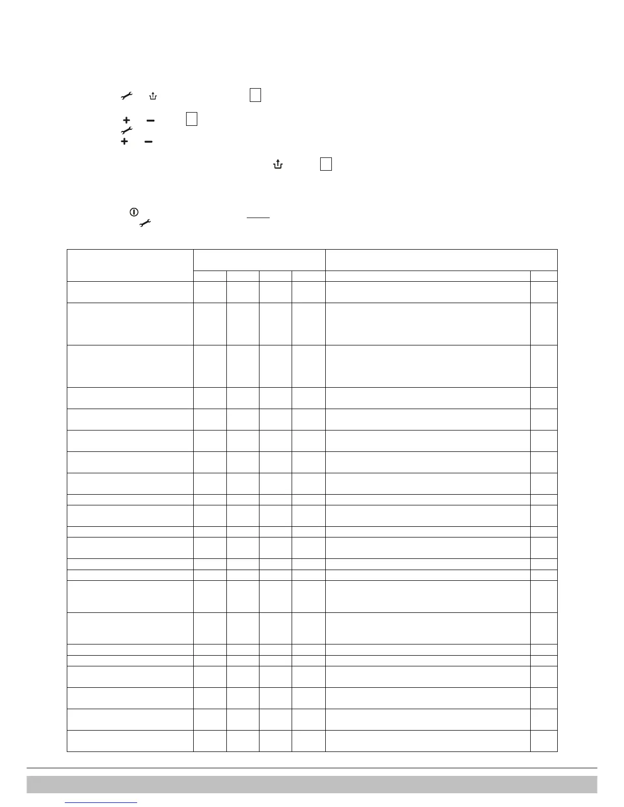
10.3 Parameters
Compact HRE SB
Factory settings
Setting 18 24 30 40 Description Par.
Service code [15] - - - - Access to installer settings
The service code must be entered (= 15)
0
Installation type 3 3 3 3 0= Combi
1= Heating only + external DHW tank , see § 8.2
2= DHW only (no heating system required)
3= Heating only (for S and Y Plans)
1
CH pump continuous 0 0 0 0 0= post purge period only
1= pump continuously active
2= pump continuously active with MIT switch
3= pump on with external switch
2
Maximum CH power set 85 85 85 99 Adjustment range of set value parameter c up to 85% or
up to 99 (HRE SB40 only)
3
Maximum DHW power set 85 85 85 75 Adjustment range of set value parameter d up to 99% or
75 % (HRE SB 40 only)
4
Min. supply temperature of the
heat curve
25 25 25 25 Adjustment range 10°C to 25°C 5
Min. outside temperature of the
heat curve
-7 -7 -7 -7 Adjustment range -9°C to 10°C 6
Max. outside temperature of the
heat curve
25 25 25 25 Adjustment range 15°C to 30°C 7
CH pump post purge period 1 1 1 1 Adjustment range 0 to 15 minutes 8
CH pump post purge period after
DHW operation, see & 8.2
1 1 1 1
(N.a. for Combi Compact appliance)
9
Booster 0 0 0 0 N.a. B
Step modulation 1 1 1 1 0= step modulation off during CH operation
1= step modulation on during CH operation
C
Minimal CH rpm 30 30 30 20 Adjustment range 25 to 50 % (40 = propane) c
Minimal DHW rpm 30 30 30 20 Adjustment range 25 to 50% (40= propane) d
Min. Supply temperature during
OT demand
(OT= OpenTherm thermostat)
40 40 40 40 Adjustment range 10°C to 60°C E
OT response 1 1 1 1 0= ignore OT if < E
1= limit OT if < E
2= OT on-off
E.
Start rpm CH 70 70 70 50 Adjustment range 50 to 99% of the set maximum rpm F
Start rpm DHW 70 70 70 50 Adjustment range 50 to 99% of the set maximum rpm F.
Max. fan rpm 45 44 48 65 Adjustment range: nominal value ± 200 rpm.
With this parameter the maximum rpm can be set
H
Set point CH (flow temperature)
during heating external DHW tank
85 85 85 85 Adjustment range 60°C to 90°C n
Waiting time after a DHW demand
before a CH demand is answered
0 0 0 0 Adjustment range 0 to 15 minutes
Not applicable for SB & OV boilers
o
Anti cycle time
5 5 5 5 Adjustment range 0 to 15 minutes P